BOOSTING THE OPERATING RANGE
option 1: ( Large increase in operating range )
The integral antenna in the Uniden series of UHF handheld radios is most
certainly a compromise.( as it is in most portables) It is a balance
between making the radio small and portable yet try and pull as much range as
possible using the available battery capacity , Transmit power and receiver
sensitivity. Although I show the modification on a Uniden handheld the
principal is applicable to any radio .
If you are lucky enough to have a GMT TX630 with a screw off antenna all you
need is an SMA male to BNC adapter to connect the UHF CB antenna cable and you
dont need to read any further !
This is a modification to enable the use of an externally mounted
gain antenna to achieve huge increases in operating range when compared to
using the radios' integral helical. It involves minimal disruption to the
radio such that it can be returned to normal (The radio still runs off its own
internal batteries.)
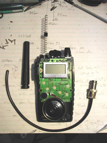
Required components coax through plastic antenna
To dismantle the radio, remove the batteries and the four screws at
each corner of the battery box and pop the case open at the sides using a
thin but wide bladed instrument. Open the case fully by hinging it open
such that the "hinge" is along to top of the radio, the antenna cover
will actually pull off( this may vary from radio to radio so don't force
things too much) see where it locks into the top of the case by a
channel. You will probably have to drill a hole in the very top of the plastic antenna cover, large enough
to take your thin coax cable as a FIRM fit , and thread the coax up through the plastic
antenna.
Undo the screw that holds the helically wound antenna to the
circuit board ( if it is held by a screw, some are just soldered), Carefully unsolder the antenna from the circuit board, noting
where it connects and where you will have to re solder the centre
wire of the 50 ohm coax. Use coax that has multi stranded
centre, it is less likely to break with constant movement compared to solid core
coax. ( the reason for the firm fit of the coax in the top of the antenna)
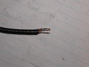 Tinned
coax
Tinned
coax
I used a piece of thin 50 ohm coax about 800 mm long ,( its what I had around) at one end it had a female BNC connector , so it could mate up with the male BNC connector on the antenna feed line. I tinned the braid and centre conductor at the other end , about 8mm long, the braid will solder to the metal frame work at the side of the PC board as strain relief, (so the antenna connection on the pc board will not pull the copper laminate off over time), and the centre conductor to the original connection point of the helical antenna
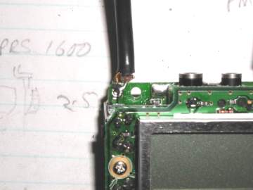
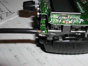
coax soldered to antenna connection side view
. Note: the antenna soldered connection was off set towards the left
side of the radio with respect to the plastic antenna cover. so your coax
is going to have to slope towards the middle of the radio so it can enter
up the hollow plastic antenna, bend it that way before you solder it.
Examine your soldered joints carefully to make sure there are no short
circuits between the fine copper braid and centre conductor.
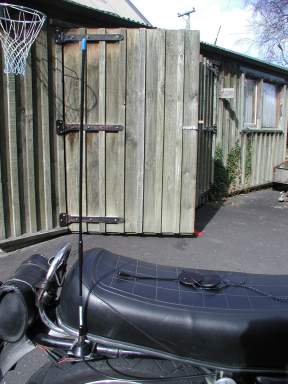
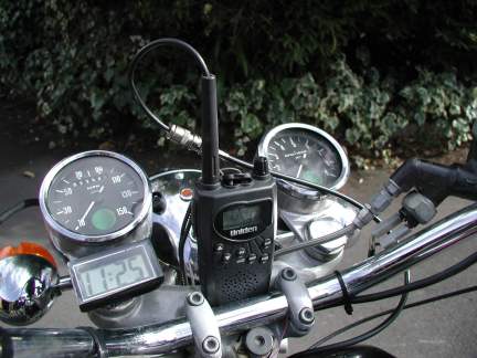
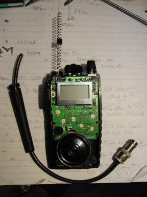
Antenna mounted at rear of Bike modified Uniden with coax out of antenna
The external antenna I used is a UHF CB 4.5dB gain vertical collinear purchased from Dick Smith. It has an integral base and 3 meters of coax terminated in a BNC connector . You don't have to use this particular antenna, as the article is only a guideline, feel free to substitute any brand of UHF CB antenna if you want. but it must be designed for 476 Mhz ( Australasian CB frequency ) not a combined VHF/UHF antenna ,they are for scanners , Find a suitable position on the bike to mount the whip such that you can get your leg over ( the bike) and not knock the antenna off every time you dismount. The antenna is mounted on a piece of 2mm thick aluminium strip and bolted to the frame of the 'cycle to achieve a good earth connection . Some antennas require a small ground plane consisting of a disk with a radius of a 1/4 wavelength or four or more quarter wavelength radials to decouple the coax from the antenna . In this instance I don't think its worth going to the trouble and complexity for the amount of extra performance it will give.
Well that is it , a good morning project , With some of the newer motorcycles (not the old clunkers like I ride) it may be a little more difficult to mount the antenna against solid metal. However if you lash out and buy one of those ground-plane independent antennas, then you can just as easily affix it to fibreglass or plastic on the motorcycle without degrading its radio performance. (There is no reason it couldn't go on the front instead of the back) . The main advantage in the project is it makes more efficient use of the radios' signals by having a more efficient antenna ,This will be noticeable on receive as well as transmit and with a system like this, a 0.5w radio can run rings around a 5W handheld (with its own integral antenna ), particularly in receive mode ! you will hear stuff loud and clear that may not even break his mute! you will notice a HUGE improvement in readability and range and it will cost you no more in battery operating time !! let me know how you get on!!\
OPTION 2:
( moderate increase in operating range )
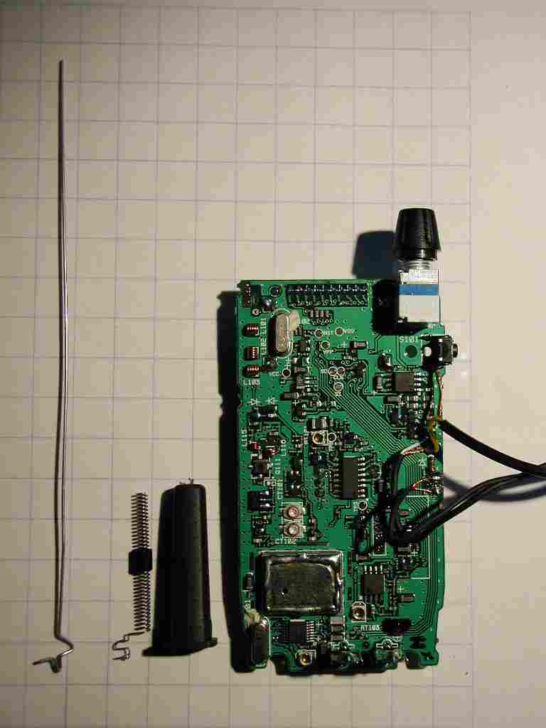
I have replaced just the "spring" antenna with a thin
stainless steel quater wave whip ( about 150 mm long at Australasian
Frequencies (476 Mhz) .This not such a difficult job , make sure you put a
small loop shape at the end of the wire so you don't get poked in the eye !( a
one eyed motorcyclist may have trouble judging distance ?? ) IMPORTANT
>>>Use
about 10 mm of fine multistranded hook-up wire between the connection of
the pc board track spring antenna soldering spot and the base of the
150mm stainless whip for potential strain relief.
Dont solder the base of the
150 mm antenna straight to the PC board , with use of the radio , you will put
strain on that soldered joint and it will break, ripping the copper track
off the pc board. This problem is harder to repair!! bend some good size sized ZIG
ZAG shapes in the base of the antenna wire so you can jam it tight up into the
old handheld plastic antenna spring cover , drill a hole in the top to poke the
antenna out of ( put the ring in the tip of the antenna AFTER you poke it
up through the hole in the top.) this antenna mod, if done to two radios
will usually allow you to squeeze another +1Km out of a pair of radios that already
do 3 Kms ( now 4 Kms!!) we have made the antenna more efficient and its
cost us no more in power consumption !
You will need some acid flux ( Duzzal etc or Killed spirits of salts ) to
solder to stainless steel , make sure you wash the soldered (tinned ) end well
to remove all traces of acid , otherwise it wont be very kind the insides of the
radio ! Note: both these mods will invalidate the radio
warranty
Unless you purchase a Uniden 075 or a GME TX610 whose
antenna connection is SMA and can be just screwed off and the coax
connected ( Dick smith, Altronics or Jaycar sell SMA to BNC
adapters )
Want to go back to Motorcycle communications? ...... click here!
Pinfold Health Services Ltd,1172 Arawa St, Rotorua 3201,New Zealand. ph +64-7-3488850 fax +64-7-3486555 pinfold@xtra.co.nz
return to CONTENTS page