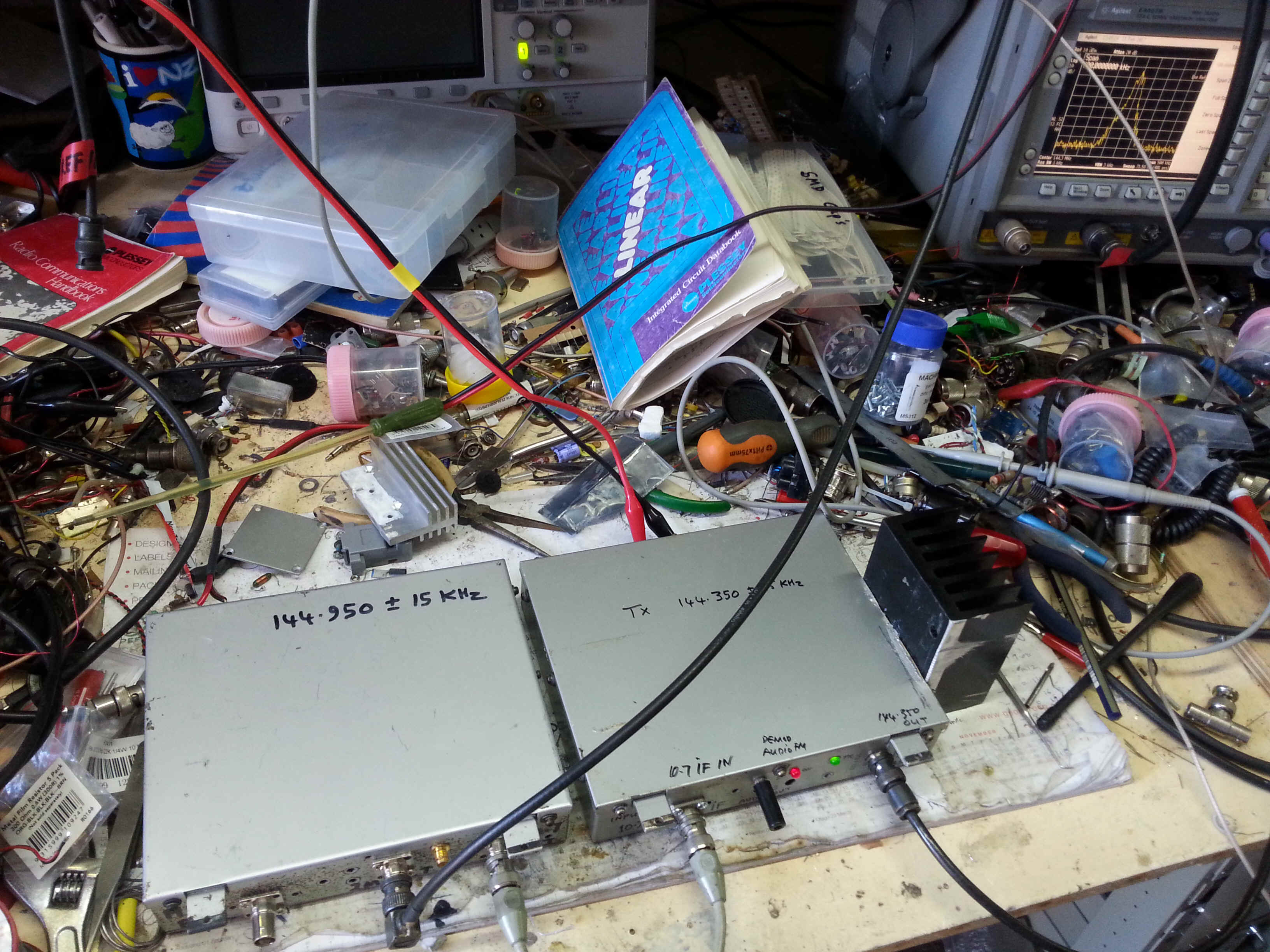
Rotorua Linear Repeater MK2 March 2017
The original repeater whose photo appears in the original web write up was built over 20 Yrs ago but was destroyed in 2015 when a psychiatrically disturbed local individual broke into the Branch 33 Rotorua Club Hut , took out all the equipment and burnt it. The system was temporarily replaced with a recrystalled Tait 172 E band VHF receiver donated by a local Ham Charlie Tetenburg ZL1BQJ. I built a 10.7 to 28MHz up converter and then hung an old yeasu ten to 2m transverter obtained from ZL1TBG on the end . This got us up and running quickly but I always wanted to replace it with a better performing unit so I rebuilt the original units in ôWarkworth ô boxes supplied by Ralph ZL1TBG many years ago. The input to the repeater is 144.950 MHz and the translated output at 144.350 MHz ,The rebuild enabled me to look closely at the concept and optimise the new design.
Over the previous months I spent many hours scanning through the web reading other folks web sites, jotting down ideas and findings . so i can say there are many parts of the design i have lifted from others and also there is content in here of my own design and experiences so if there are ideas and concepts you recognise from your publications thank you for sharing it with me via the w.w.w..
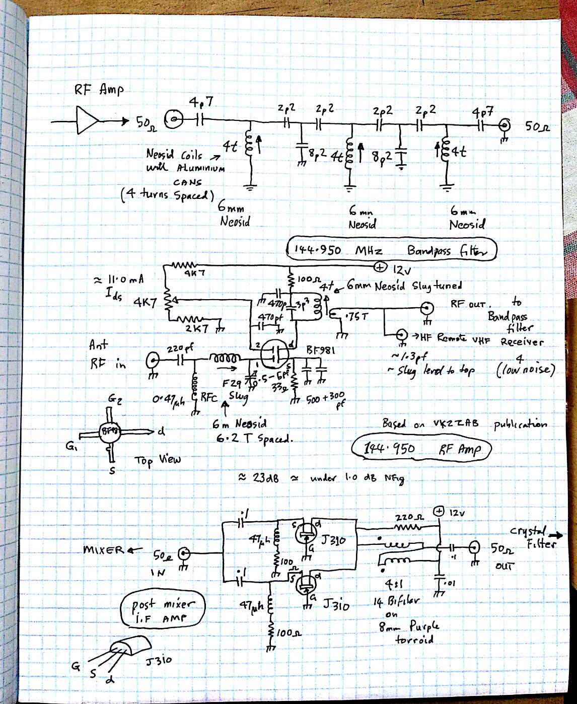
The front end is a low noise BF981 followed by a bandpass filter with an
additional tap off after amplification and filtering .This is to enable sharing
of the repeater receive antenna system and not have use a 3 db loss inducing rf
splitter in the receive feedline , this output is for the HF control receiver on
145.000 MHz .
The mixer is an high level +17 dBm passive double balanced one with 50 ohm termination on all
ports .the IF output passes trough a 50 Ohm diplexer to maintain termination and
then into a pair of grounded gate Jfet amp to isolate the mixer from reactive
reflections off the 30 Khz crystal filter .
The I.F Unit
( the first iteration!! )The intermediate frequency is at 10.7 Mhz mainly because I have the quartz
crystal filters to enable a 10.7 Mhz I.F and I have two that are 30 Khz wide ..
I settled on 30 Khz hopefully to enable fidelity for digital modes. Locals are
getting into Dstar etc ...
Being a Linear Repeater and able to pass any modulation mode means the i.f has
to be AGC controlled .So I settled for an old favourite which I have used before
and it is based on the now defunct Plessey range of Integrated circuits made
specially for two way radio communications .For SSB/AM they produced a couple of
work horses that used a minimum parts count and functioned extremely well . Most
work with a 6-9 Volt rail and tens of mA consumption , I used the SL1612 i.f
amplifier and its RF controlled AGC chip the SL1623. They do have a better audio
derived AGC device for SSB, the SL1621 but since this repeater will be handling
FM as well, a carrier derived AGC was more suited compromise .
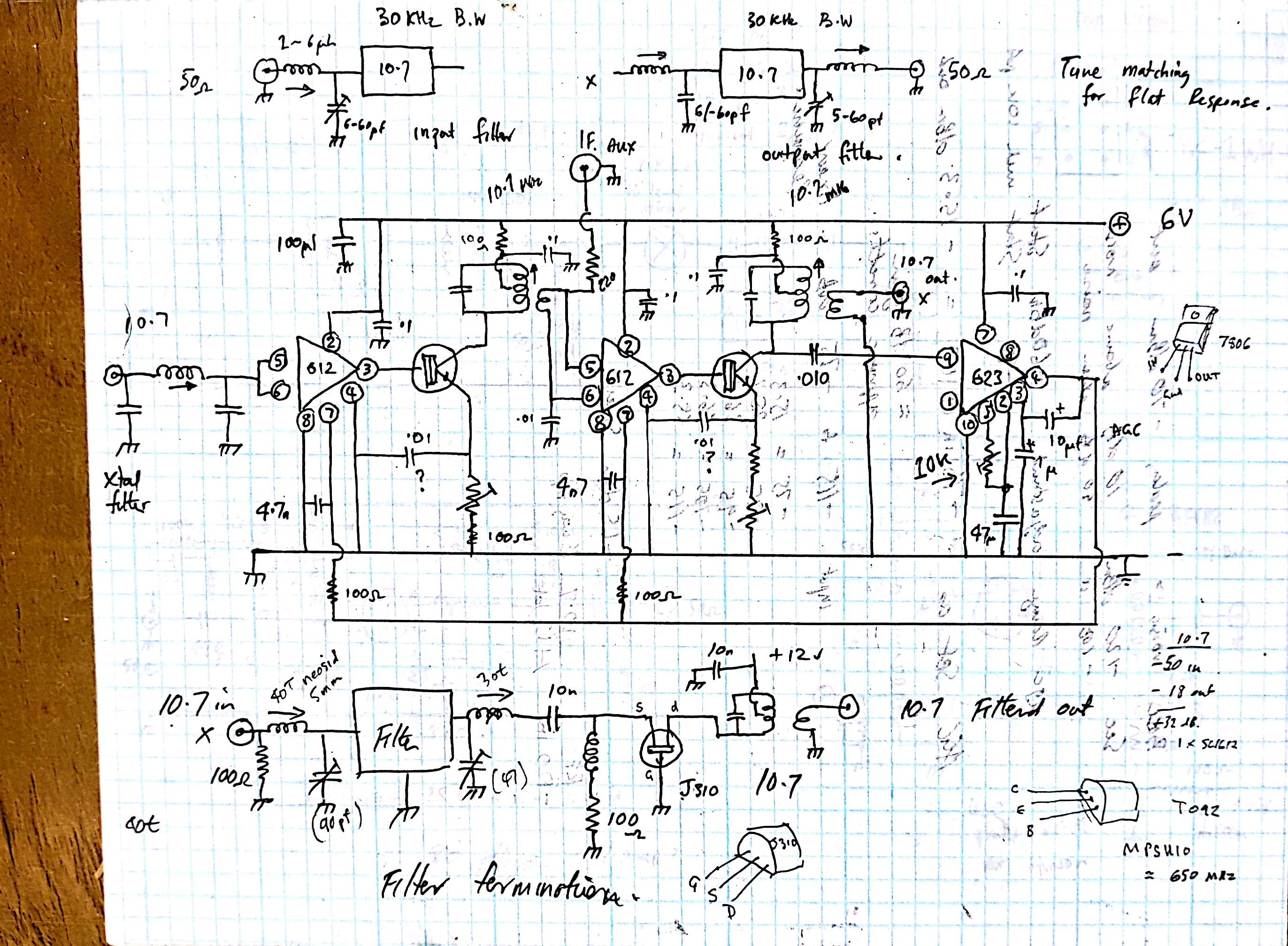
The input to the i.f amp board is 50 ohms and feeds directly into a mult-pole
30 Khz wide crystal filter correctly matched via a simple L network to achieve
an almost flat ripple free band pass ,There is a relatively simple way of
ascertaining the unknown impedence of a crystal filter using a sweep
system , two 4k7 variable resistors and 50 ohm terminations , the rf
output of the sweep analyser system is terminated at the and of the coax
that feeds the filter . the braid connectes to the earth side and the 50 ohm
terminated centre conductor connects to the centre wiper of the 4k7
variable resistor either of the end of the track connects to the crystal filter
input ( do this at the output as well} play around with the variable
sestors until you obtain a flat passband response , dont worry about
the losses present , measure the value of resistance that gives the flat
passband.. that is an approximation of the filter impedance with a
few random pf across the filter . Its enough to get you into the
balpark and design an L matching network ! ,thanks to WD4HXG
chuck for writing
this up and putting it on the web!!
The output of the filter is matched via a simple Pi network into the first AGC controlled SL1612 amplifier ( with a gain of about 34 dB) , the output of the 1612 feeds straight into a MPSH-10 transistor stage in order to drive the first 10.7 Mhz interstage transformer . Plessey advocate simple capacitive interstage coupling between I.Cĺs but I feel this generated too much broadband noise which would translate to the 2m RF output stage so I limit the rf band noise via a 10K dampened tuned 10.7 MHz transformer .
The Transformer link couples to the following SL1612 stage and also has a resistive tap off so RF can be removed from the IF amp unit( to a FM demodulator section ) or if required introduced from another front end source eg 10 m Front end ,into the second SL1612 and processed up to 2m ( the AGC control range is much less via this connection) . The second SL1612 is identical to the first with a similar transformer coupling at the output . Link coupling off the second transformer carries amplified i.f signal to the ĺ Lĺ matching circuit that connects to the second 30 Khz wide 10.7 MHz crystal filter ..The second crystal filter limits the bandwidth of any noise generated in the 65 db gain i.f strip to 30 Khz as this .i.f noise will be translated up to the 144.350 MHz repeater output frequency and we do not want to waste RF spectrum on just broadband noise, but also keep potential upmixed broadband noise away from the receive frequency of 144.950 MHz
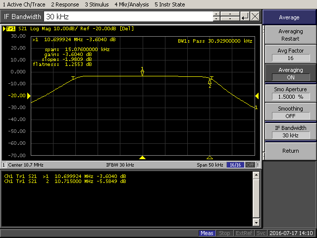
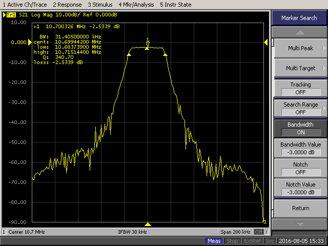
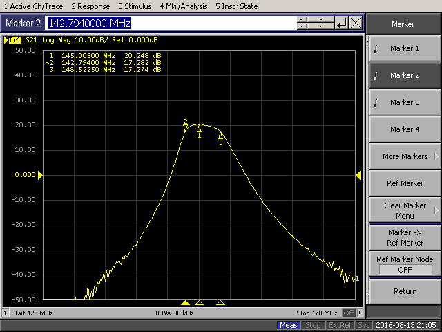
This is the swept response of the I.F at 10.7 . I was a little disconcerted to see the double hump in the pass -band but I suspect its due to the agc working, the gain changes, due to attack and release time constants ? I will examine this more closely later. At the moment I am very happy with the performance of the IF , the SL612 supposedly has a N.F of 4 db at 10.7 so it should be relatively quiet in operation.
This is minus 120 dBm into the IF unit, as you can see this level has a very good s/n !
Plessey
If output
But minus 120 dBm also produces what I will say is a useable s/n so Im not going to need bags of preamplification in the RF front end ahead of the I.F !!
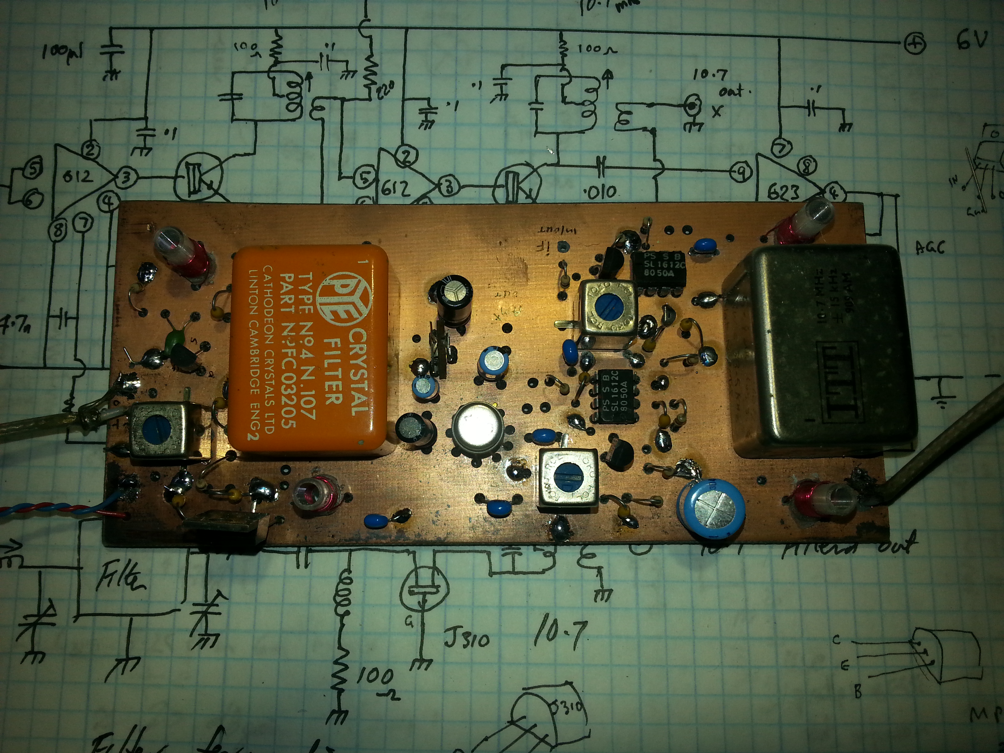
matched crystal filter
The second 10.7 MHz crystal filter is ô Lö matched to a common gate j fet stage that provides a small amount of gain but whose very good return loss provides an easy 50 ohm impedance with which to match to, thus maintaining the flat passband characteristics of the ô bandwidth tail noise limitingö crystal filter .
I should have used 3 of
SL612 !!!
And Now the faux Pas .. It was not until I was designing the 10.7 to 144.350 up mixer did it dawn on me I had made a blunder with the IF amp . The original 10.7 IF amp in the repeater that was burned by the psychiatrically disturbed one had 3 SL612 IF amp chips , giving a total stable I.F gain of over 100 dB , on double side pc board without extensive shielding (good ol plessey they knew how to make great RF stuff) .
Thus previously I had a designed and well thought out system with about 15.db of headroom, from broadband IF noise output and the start of full on agc ,This gave me a 15 db range in the transmitted RF output from an input sigal of less than ľ127dbm to -112 dBm where the agc now is fully on and controlling the receiver gain . I tried to close the agc range into the upmixer with another outboard I.F amp with its own extra AGC but ran into a mass of trouble with both IF interacting ,in the end I gave up and redesigned the receiver I.F board ..I needed over 100 db so I had a small bucket of Siemens BF960 UHF dual gate mosfets and pressed them into action .Three stages will give me a total of 104 db I look up the net and found a lot of IF amps use almost direct broadband coupling from a RF choke in the drain how ever I decided to use bandwidth limiting 10.7 MHz interstage IF transformers on the input ,to couple each stage and the output .and design my own RF derived AGC to control them .
I am trying to minimise the amount of broadband IF noise generated in the Amp so as the Upmixed RF wont be drowned in the signal generated by the IF contribution and also cut down on the amount of unnecessary broadband rf output.. After much reading on the net and QST magazine articles , it was decided to use red LEDs as reverse bias generators in the source of each BF960 stage ,This trick enables you to apply more AGC control voltage than simple source resistor bias and achieve even greater AGC range ..something I lacked in the previous amp .
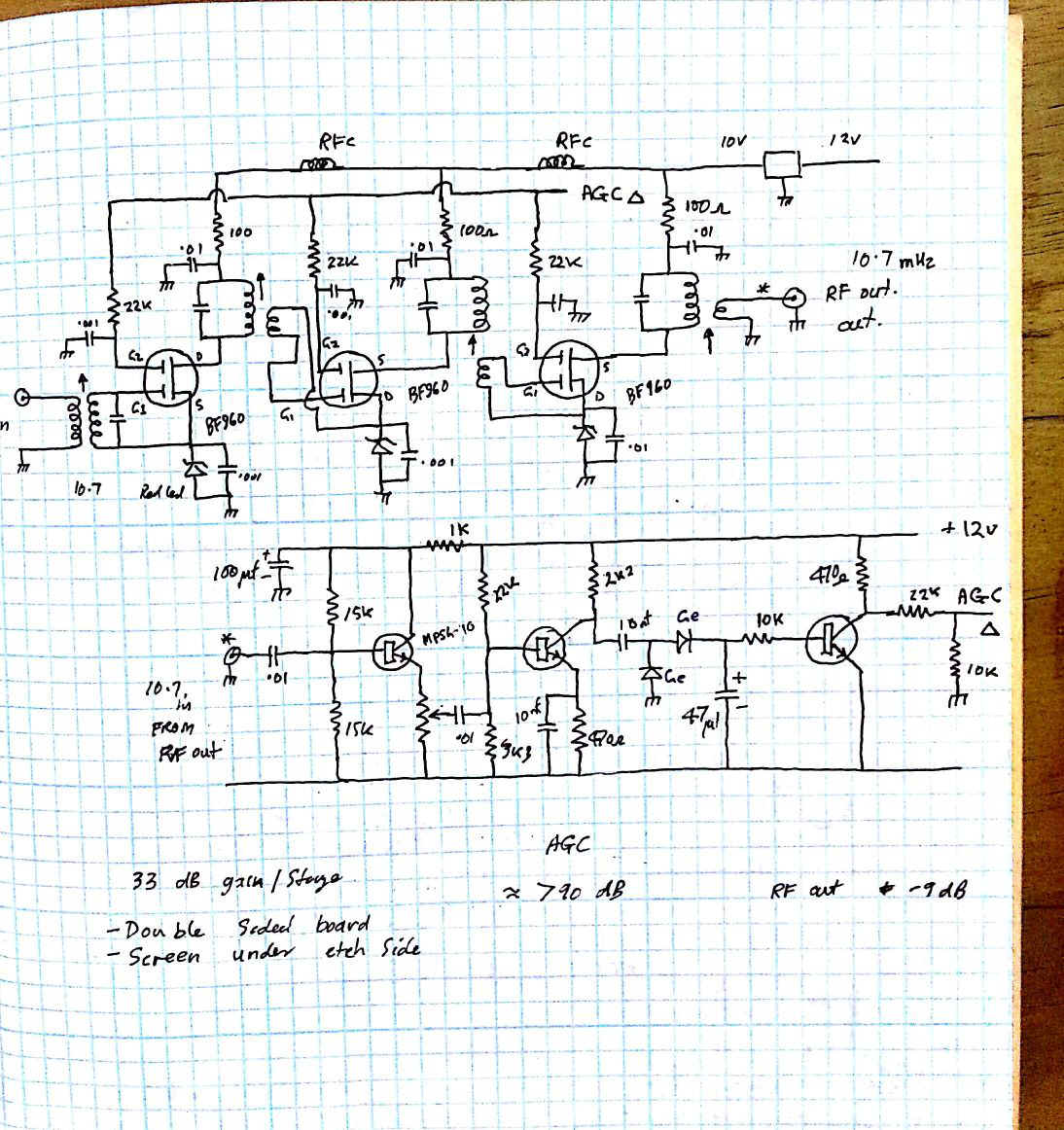
Second iteration of the 10.7 IF
amp
So I built up a standard three stage IF amp along the usual mosfet Amp designs on double sided PC board and used manual control of the IF to see how tame the Amp was ..well it was not ! It was a reliable oscillator at around 10.7 MHz at high gain setting. Some of the IF tuning was quite peaky and sharp indicating some sort of regeneration was attempting to take place . Stagger tuning helped stability but I did not want to use that as a mechanism to exert control . I then set about biasing all the RF points as much as practical ..RF chokes in the B+ leads to each stage the odd 10k resistor across tuned circuits t o dampen things down and it still looked like it was ready to explode on the spec an screen, tuning was still very peaky , The RF was till getting from the outpuit to the input !100 db is a lot of gain in a small area !! it wasnĺt until in an act of final desperation did try close shielding of the printed circuit side of the board with some thin shaped brass shim sheet soldered to the ground plane topside that everything settled down and the amp became useful . I then made up a simple RF generated AGC control circuit with a good load resistor on the AGC line and we were in business .The Agc could be made to kick in very early in the piece when the RF input was still quite low level and thus I had obtained my small dynamic range of potential RF output from 100 mW up to almost 10w at 144.350 MHz. The next thing was to redesign the L match to connect the two 30 Khz BW I.F filters to the input and output of the 10.7 MHz I.F
10.7 MHz if filter response
My only concern with these old wideband crystal filters is the overall stop band is not that good compared to narrower, more modern multipole filters, These have a better stop band and shape factor, Using these wideband filters can potentially make the system more susceptible to out of band nearby interference , but we are lucky here in Rotorua we are a long way from high power signals .
Linear Repeater
Front End
The line up is as follows. RF input matching configured for minimum noise ( under 1 dB, hopefully 0.7! ) into the BF981 dual gate Mosfet , this is a design published on the net by VK2TAB , I have changed the output to a simple link coupled tuned circuit. The BF981 provides a measured 23 dB gain , more than enough ůThe output of the BF981 feeds a three section series filter with a loss of 3 dB and good stop band performance to eliminate the image frequency .
( The image frequency must be suppressed by at least 16 db or the presence of the image frequency will increase the noise figure of the rf amp by 3 dB .)
I decided to use a high level +17 dBm passive double balanced mixer for good intermod performance. ( and because I had some too !)The mixer was terminated as is recommended in 50 ohm matching, to guarantee this , 6 db attenuators where placed on the rf and local oscillator ports . The I.F port was terminated with a 50 ohm grounded gate j310 in push pull amp, this feeds the 30Khz wide crystal filters via a ôLö matching circuit. The jfet amp provides a 50 ohm buffer between the High level mixer and reactive 30 KHz crystal filter via its matching network .
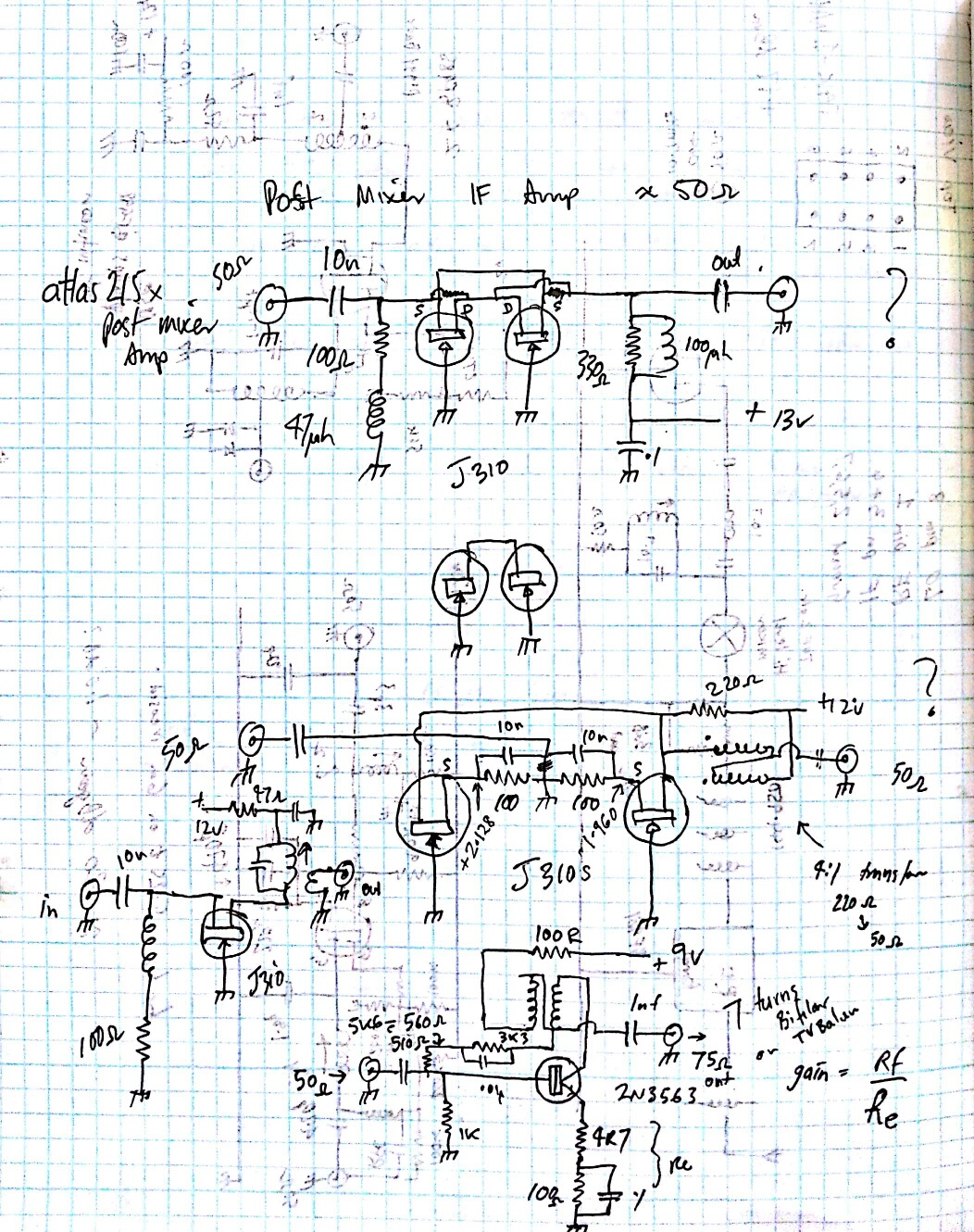
50 Ohm Jfet amps
Three section post Rf amp
bandpass filter
The rf output of the three section bandpass filter also has a tap off , which will be brought to the the outside of the receiver as a female BNC, for connection of the 145 Mhz command receiver ( icom 2a) for remote controlled HF receiver ICR75. That way we do not have to use an external antenna signal splitter to share the repeater receive antenna for the 145 Mhz control ic2A receiver and suffer the additional 3.6 dB loss and thus an increase in noise figure of the repeater receiver. And also the 145 MHz control signal will just sneak through our 144.950 receive filters !
145 Mhz control frequency response of repeater filters
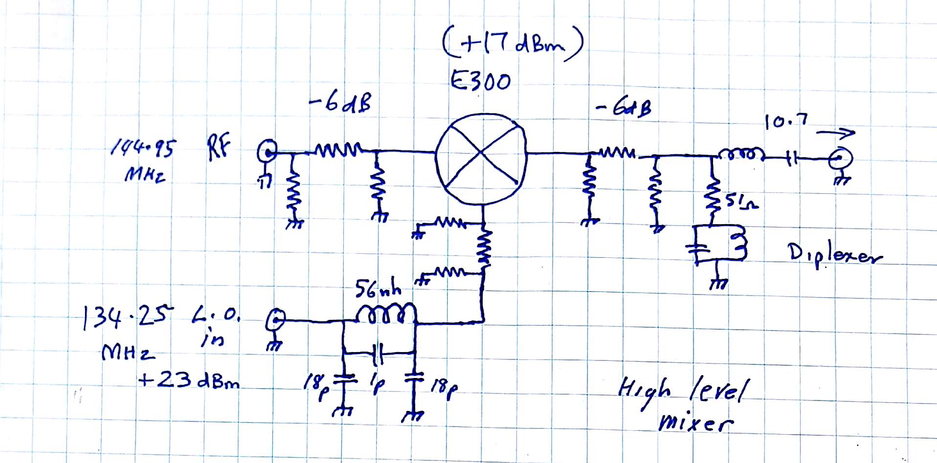
The mixer is a high level +17 dBm minicircuits unit with low noise and high third order intercept, ( provided the mixer is terminated in 50 ohms at all ports) To achieve this, the mixer is terminated with 6db pads made with resistors ( although you can purchase smd pads !) in the RF input port and L.O. port ,the I.F output is terminated in 50 ohms via the frequency selective diplexer circuit that passes the 10.7 MHz to the IF amplifier and diverts other mixing products to the 50 Ohm termination thus keeping the mixer happy!
simple 50 diplexer
.
10.7 Mhz diplexer
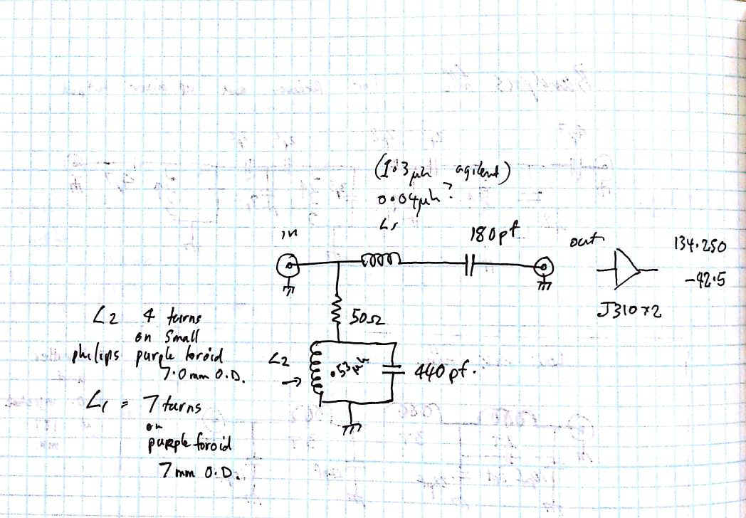
The +23 dBm L.O signal is passed through a simple 3 pole low pass filter to clean the 134 Mhz injection frequency then through a 6dB pad before it enters the E300 Double Balanced Mixer .
The output of the mixer passes
through the diplexer to a dual J310 Jfet grounded gate broad band amplifier with
a gain of a few dB, but its main
use is to isolate the mixer from
the reactive components generated
by the out of band frequencies reflected from
the crystal filter ..The 50 Ohm output of the jfet mixer connects to
the ôLö matching network that connects to
the first 30 KHz wide
crystal filter and gives it a flat pass band .
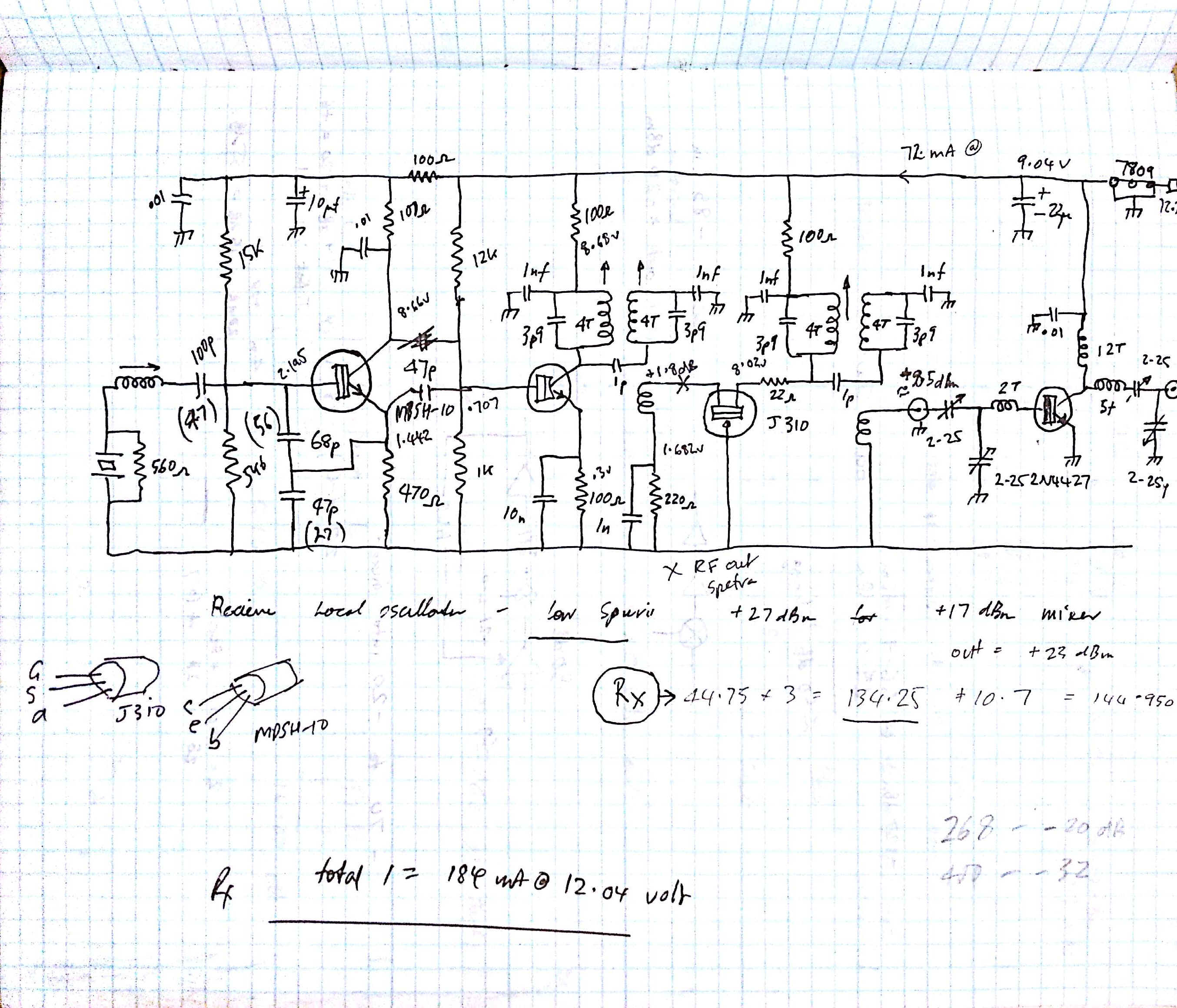
Circuit of receiver L.O rf chain ůůůůůů
This RF feeds the L.O port of the
mixer via a pi configured caur low
pass filter to attenuate higher harmonics
.
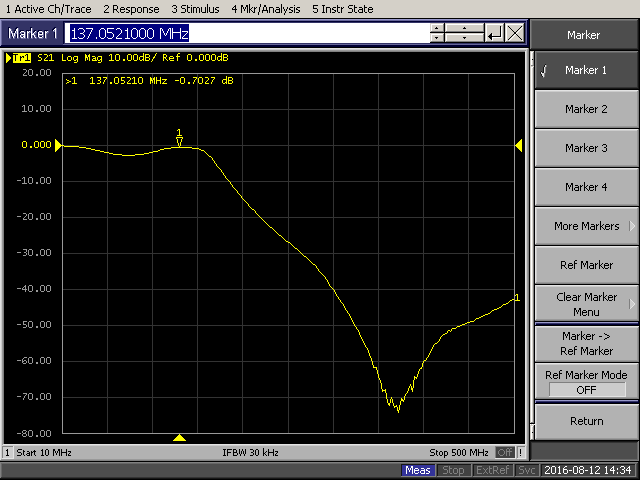
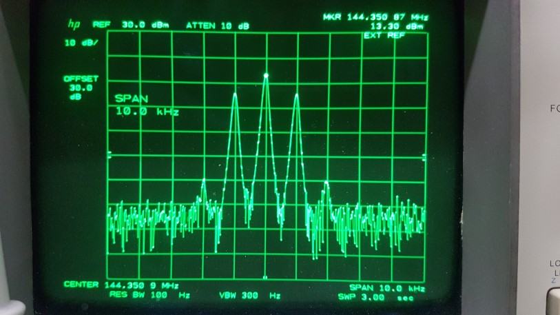
I decided to place voltage control on the osc to maintain stability and used a three terminal 10v low drop out regulator to achieve this.. Be wary of the effects of voltage regulators especially LDO types , they have high feedback gain . and they can be prone to instability despite using the recommended capacitive bypass on the in and the out .This was a problem I had with my Rx osc chain causing this spectral output on the transmitted signal
YIKES !! This was a spectrum plot of the 144.350 MHz output .
At first I thought the instability was generated in the 2m Linear amplifier output stages and I couldnĺt understand why the spurii were regularly spaced and remarkably frequency stable and no amount of tuning would change or tame the beast. So I connected a pick up loop to the spec an and started waving it overtop of the upmixer module and local osc circuitry , I turned off the 10.7 MHz drive so there was no influence from that source and low and behold the same interference was in the upmixer local Oscillator output. , so I retuned it and there was no change.
On the Spec An it looked like an AM signal not FM!.. then I put a scope probe on the 10v rail and low and behold this is what I saw !! a 4 volt sawtooth on the 10v rail ..no wonder !!amplitude modulating the local oscillator chain
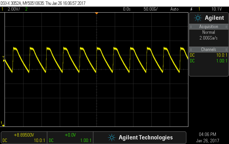
! Fixed by soldering a 10uF tantalum directly between the output pin and ground of the low drop out three pin regulator.( I had already connected the manufacturer suggested decoupling capacitors)
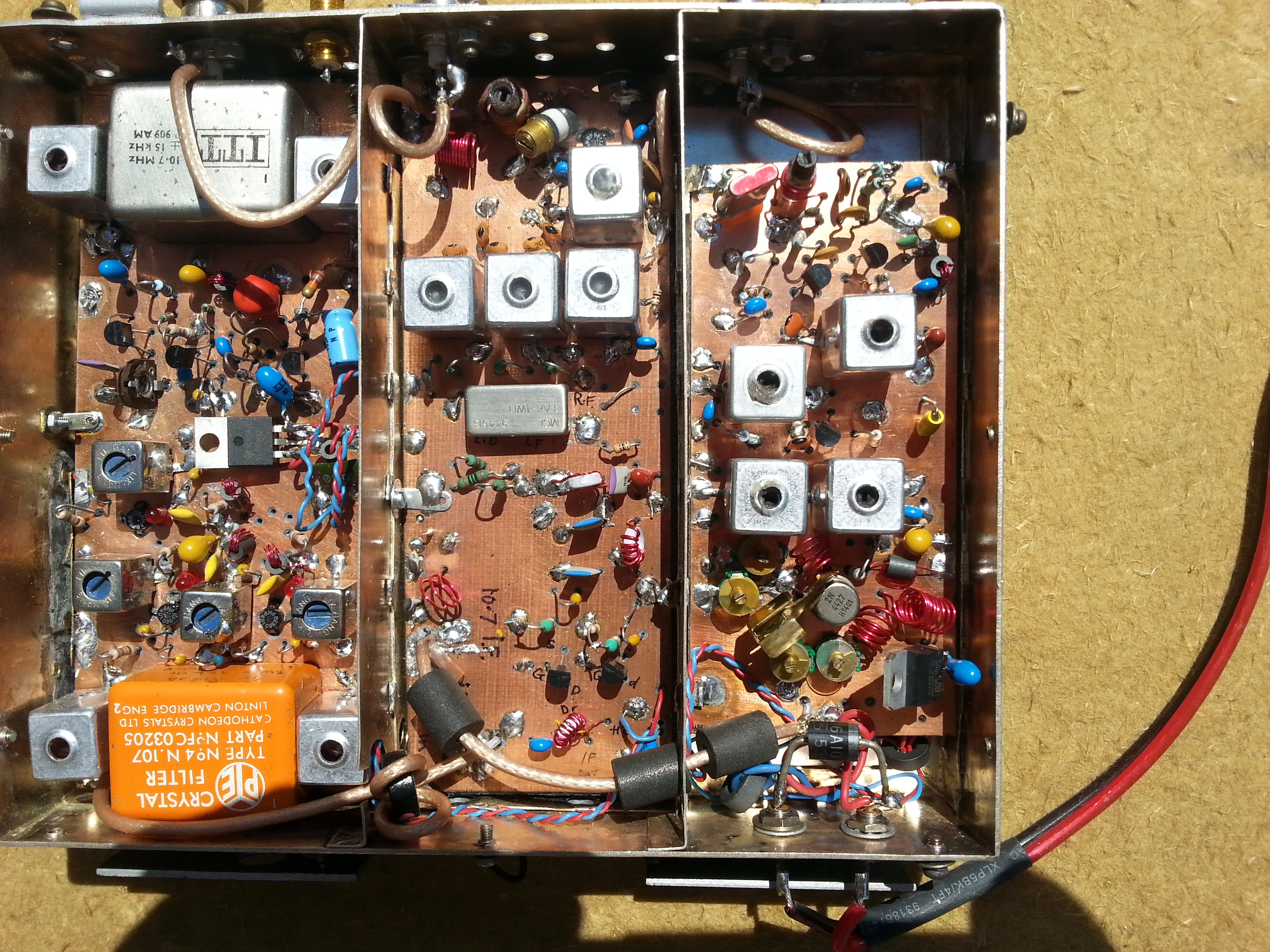
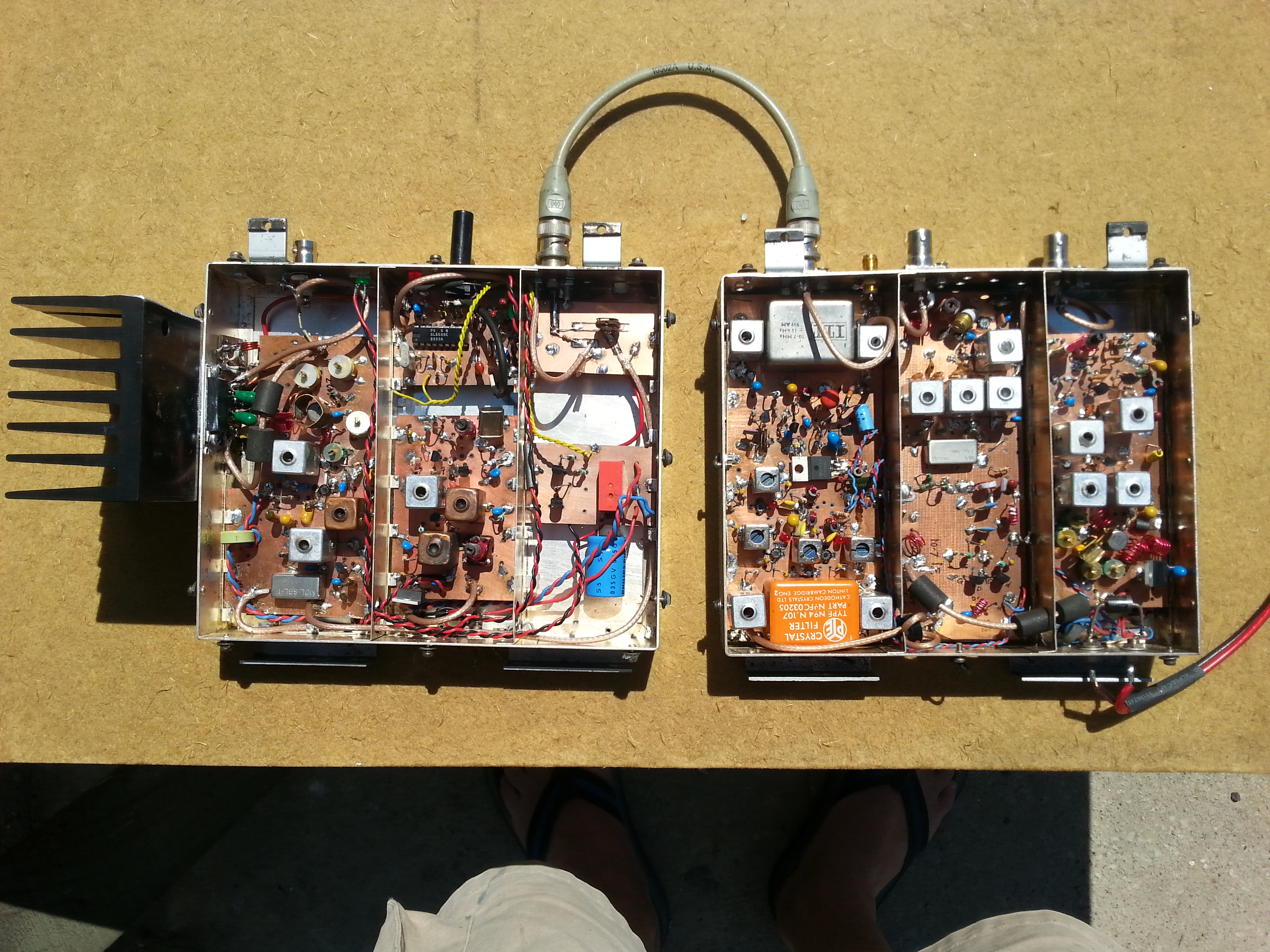
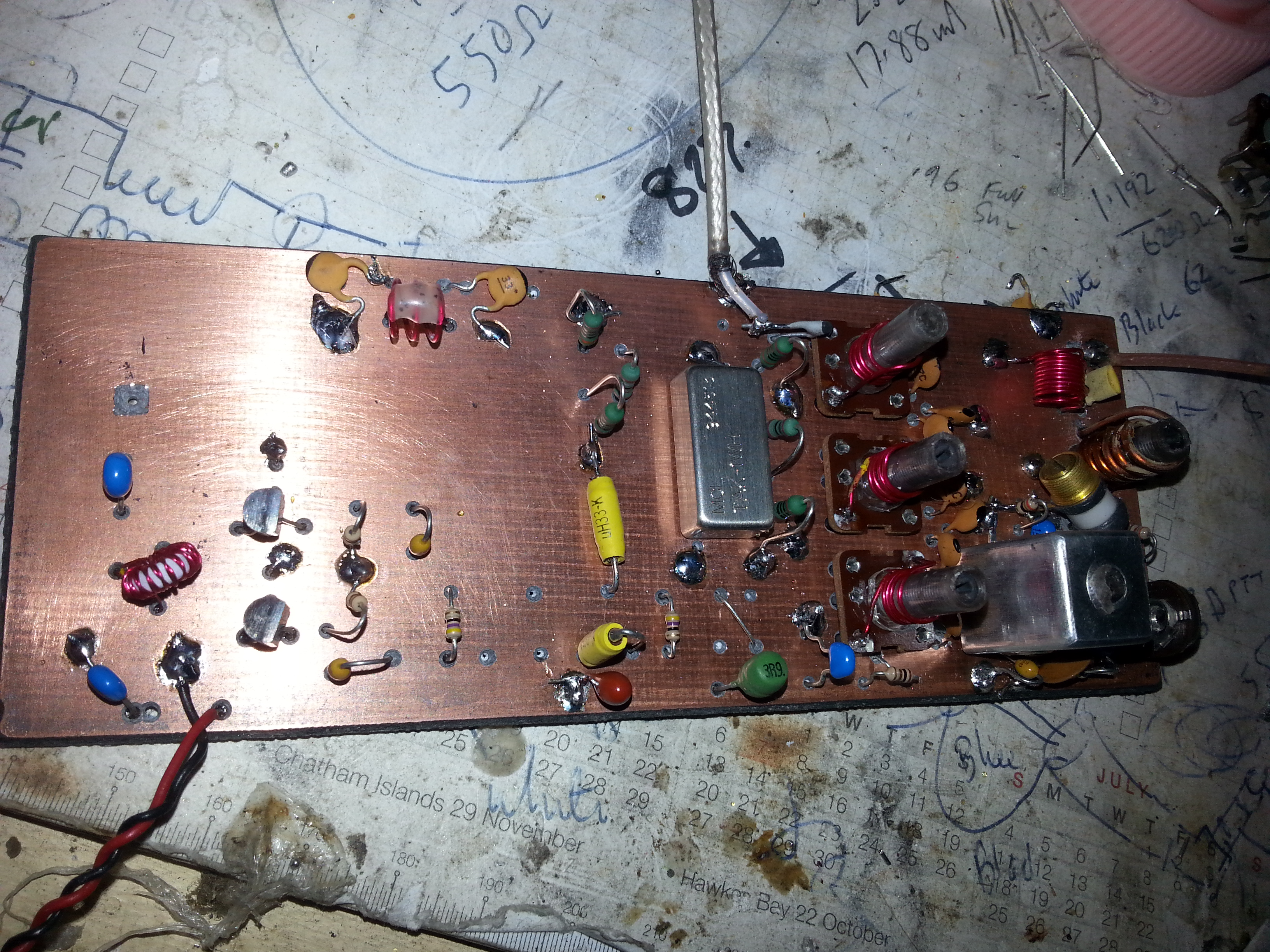
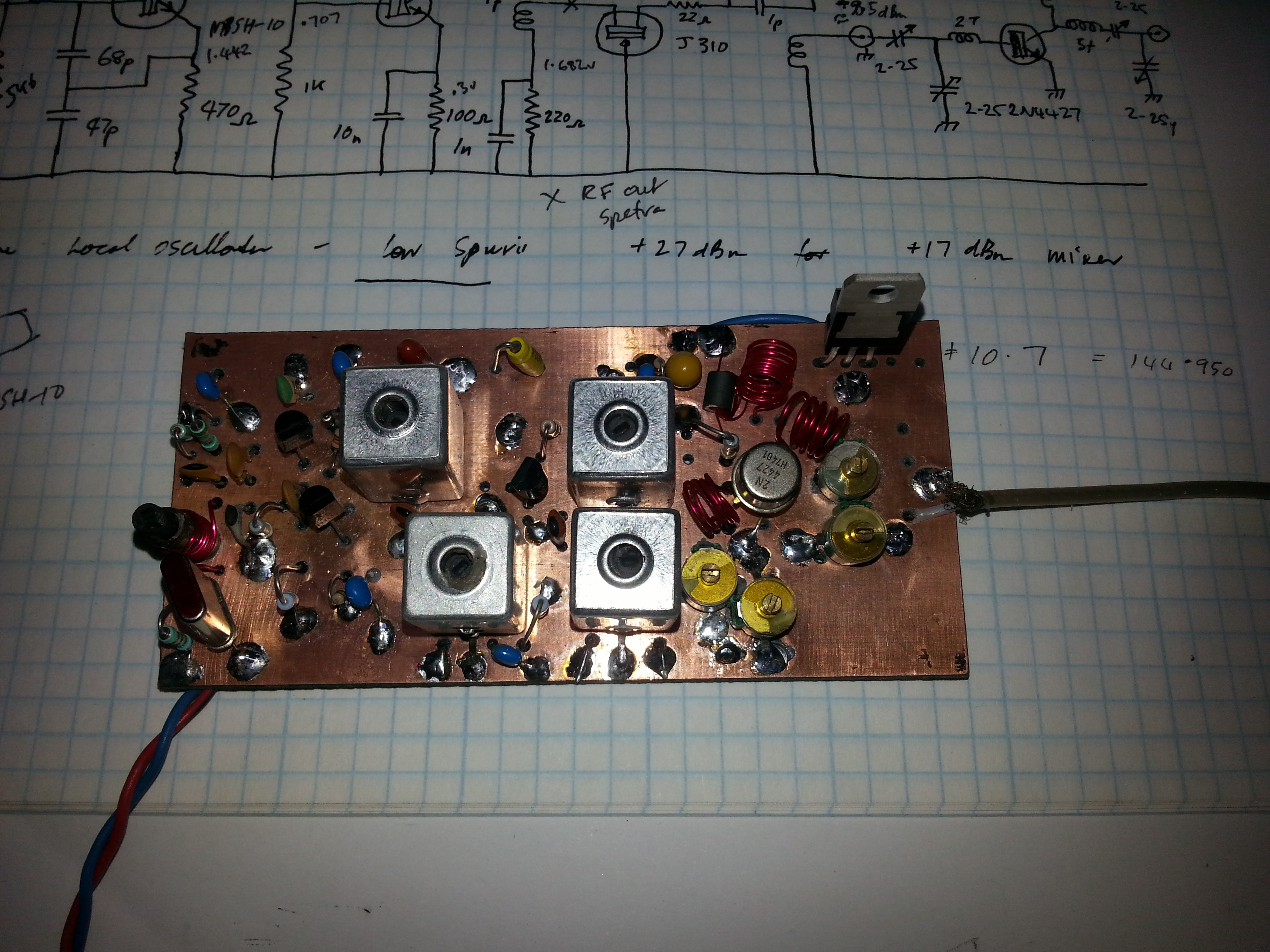
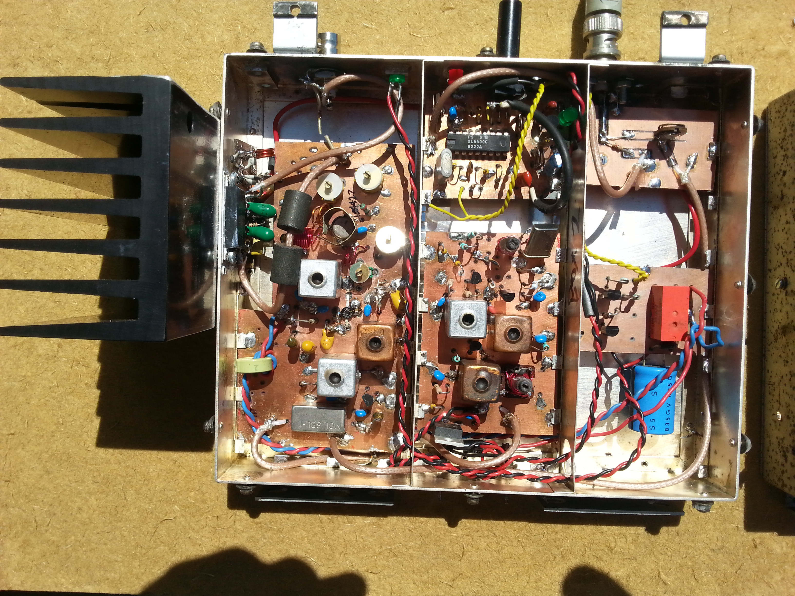
Finished Receiver for 144.950 MHz with 30 KHz if filters
The RIGHT hand section is the high level mixer local oscillator with +23 dBm Rf output at 134.250 MHz
. The middle section is the BF981 RF amplifer with three section bandpass filter , high level mixer, post mixer diplexer and dual J310 jfets 50 Ohm post mixer amp in grounded gate configuration..
The LEFT hand section is the 3 BF960 mosfet based IF amp using leds as constant voltage in the source and required carrier derived AGC
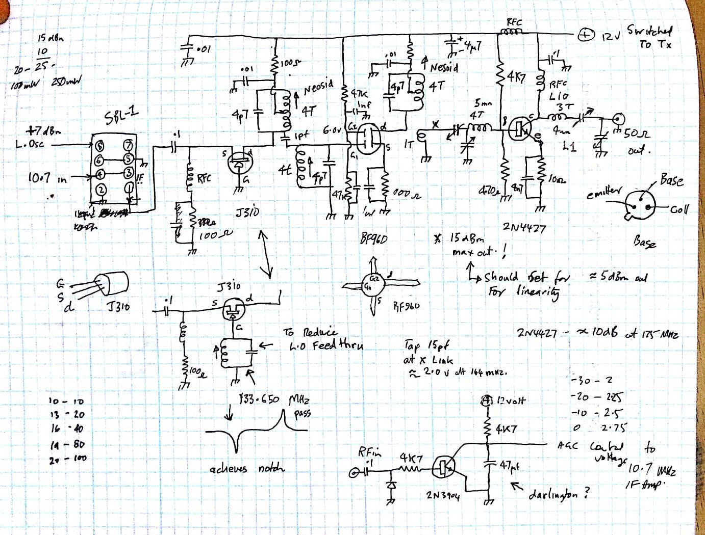
The RF Up
Mixer
After much internet scrutiny it was decided to use an SBL-1
DBM as the mixing element in this section . With the sbl-1, rf losses are low
and it has good strong signal handling ability, good balance to minimise
L.O feed through and an easy
obtainable level of RF requirement
for the local oscillator at +7 dBm with few active
components . I chose the
port that gave the greatest isolation for the 134.850 Mhz local oscillator as
this enables me to relax the amount of 144.350 selectivity . I did try
the parallel tuned circuit in the grounded gate JFet amp at the
wanted rejection frequency 133.650 but couldnt get to perform
( works well at 10's of MHz ) . so I went back to the simple amp configuration.
The up mixer linear amplifier chain consists of three stages of
amplification .
The first a common gate Jfet amplifier
(J310) with a 50 ohm input impedance to match the output of the sbl-1 DBM ,
through 2 tuned circuits to enhance 144.350 Mhz and reject the L.O up mixer
frequency leaked from the SBL-1.
This feeds a BF960 dual gate mosfet through more lightly coupled tuned circuits, for good selectivity, gain and linearity. The output of this stage feeds a 2N4427 Bipolar linear stage for an output of up to +18 dBm at 144.350Mhz . The RF output hopefully will drive a Toshiba SAV-8 Linear 2m power brick to achieve a nominal 17 W peak RF output .
Modification to upmixer RF driver
The Linear repeater was bought
down for servicing as I detected via received signal strength .It had dropped
its RF output by some 6 db's or so when stimulated by a signal sent from my
signal generator into to my 2m collinear antenna , the change in received signal
Level was seen on the spectrum analyser .
I went up to the site and swaped it out leaving the old lashed up repeater as a
replacement . When I put the repeater o the bench and fired it up I measured
just over 2 watts RF out subsequently this was traced to a burned out capacitor
in the RF lowpass filter at the output . But while testing and looking on the
analyser via a 30 dB power attenuator I noticed instabilities on the rf upmixer
driver circuitry , after much fiddling and bypassing and component substitution
I decided it would be easier to just redesign the upmixer driver ..perhaps the
instability had been there all along ?? I also noticed the high level of 133.650
MHz mixer L.O rf output in the output , a little higher than I would have liked
due to it being in the top end of the aviation band .
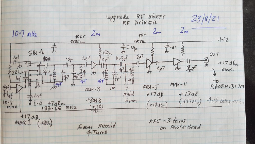
The next thing to do was work out the amount of gain I will need between the ôno
signalö 10.7 I.F level -53 dBm and the amount of signal power (+13 dBm ) I will
need to drive the 10 W rf output brick (RA08H1317M)to full power . This was
approx 66 dB ! This time I wanted to use minicircuits brand MMIC in the chain
instead of discret devices ( only because I had some) I did play around with a
BFR96 as a pre driver for the power brick but had nothing but trouble with
instability in the GHz range so avoid this device like the plague .
This time I took a different approach ,I would split up the total required gain
into two chunks, place some at 10.7 MHz and less at 2m, because the 2 m will be
the harder gain block to stabilize.My final line up consisted 10.7 into a Mar-1
(17 dB) into SBL-1 mixer then into a 2m bandpass filter Mar-8 (30dB) 2m bandpass
filter , Era-5 (18dB) then into a Mav-11 (12dB) this gives a total of 76 dB ,In
theory this will take the no signal I.F output to +22 dBm ,9db more than
enough(+13) to drive the power brick to 10W , however remember there will be 6
db loss in the SBL-1 and semi large losses in the bandpass filters , and the rf
level of the 10.7 I.F will rise to -27 dbm at full AGC . The 10.7 IF level from
the output of the receiver can be set with a pot so the Max 2m RF (+40dBm) out
can be adjusted the max I.F output of the 144.950 MHz receiver.
![]()
new up mixer driver board installed .
The measured gain of the final upmixer RF driver board was 68dB ie -46dBm in at 10.7 MHz gives +22.8 dBm at 144.350 MHz ( mute just opens... as mute circuit is in the transmitter unit ) -26dBm in gives 39.2 dBm out at 2m ( slight loss of output in the low pass filter) the apparent drop in Rf output is also due the top of the response curve of the power brick .Note to minimize this ôpower dropö in the total amplifier chain, is to pick mimics whose rf output compression point is well above the maximum signal expected to pass through the devices mimmics with low compression points at the beginning and highest at the end .The pc board was made with double sided copper , with the earth ground plane on top and used to earth components .
Upmixer Board linearity test....... 1 Khz @ 80% modulation at +13 dBm ( im happy with this)
Mute circuit
All Repeaters require a mute circuit to gate the transmitter on after receipt of a signal, The last repeater used a CA3075FM FM detector with a noise mute circuit, this switched a relay which powered up the linear amplifier stages as they are not required until a signal appears ,thus saving power in our solar powered site.
The rf oscillators are left running to minimise off-on frequency drift. I tried all types of mute circuits but none were stable tame and consistent so I looked at alternatives. Some I will investigate later when time permits . ( dual pll correlation mute ??)
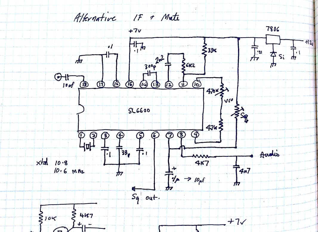
With previous experience many years ago with Plessey RF
stuff I decided to try a plessey SL6600 dual conversion
PLL based fm detector IC of which I had several .
I have always had good results with
their active components, such a pity they have gone the way of many good RF
semiconductor companies. I etched up a small board , populated it and
tested the performance of the chip at 10.7 MHz and I was impressed . ..I somehow
expected it would perform well and
the mute action was very decisive even under the
high level of broadband noise that came in along with the wanted signal
from the 30Khz wide 10.7 MHz signal
into pin18 ..the crystal is 10.6 Mhz as the pll runs from 50 Khz up to 455
Khz .
( The plessy notes give a simple capacitor value formular for PLL VCO frequency but I found I could "select on test" with a variable and get better weak signal performance )
I can have reliable muting at ľ127 dBm !!if I want
. This I.C rocks ! I also
took the audio out of the fm demodulation port in case dtmf control function is
required at the repeater site.
. The Squelch output was taken through two transistor stages so the mute
polarity shift would drive a small relay. I
finally settled on a ľ124 dBm mute open signal as this appears on the
border of useful readability of a nbfm signal picked up on the HP8920A test set
.
To generate a small ôtailö on the repeater I placed a 1000uF electrolytic across the transmit relay coil . This serves two functions, it reduces the indecision ô mute chatterö on very weak signals and places a small tail on the signals such that it may hold the repeater open in SSB contacts between voice peaks.
The relay contacts were paralleled up to increase current capability and they were used to switch +12v to the transmitter linear amplifier stages . Im sure a switching power mosfet would have been a good substitute ,but I didnĺt have any .. In the interest of dc power saving in our solar powered site I decided to use instead of the 17W Toshiba power brick , a more modern 135-175 MHz linear Power amp module ,The $21 two stage mosfet power module RA08H1317M. 20 mW in gives over 8 W out , typically 10 w into 50 ohms
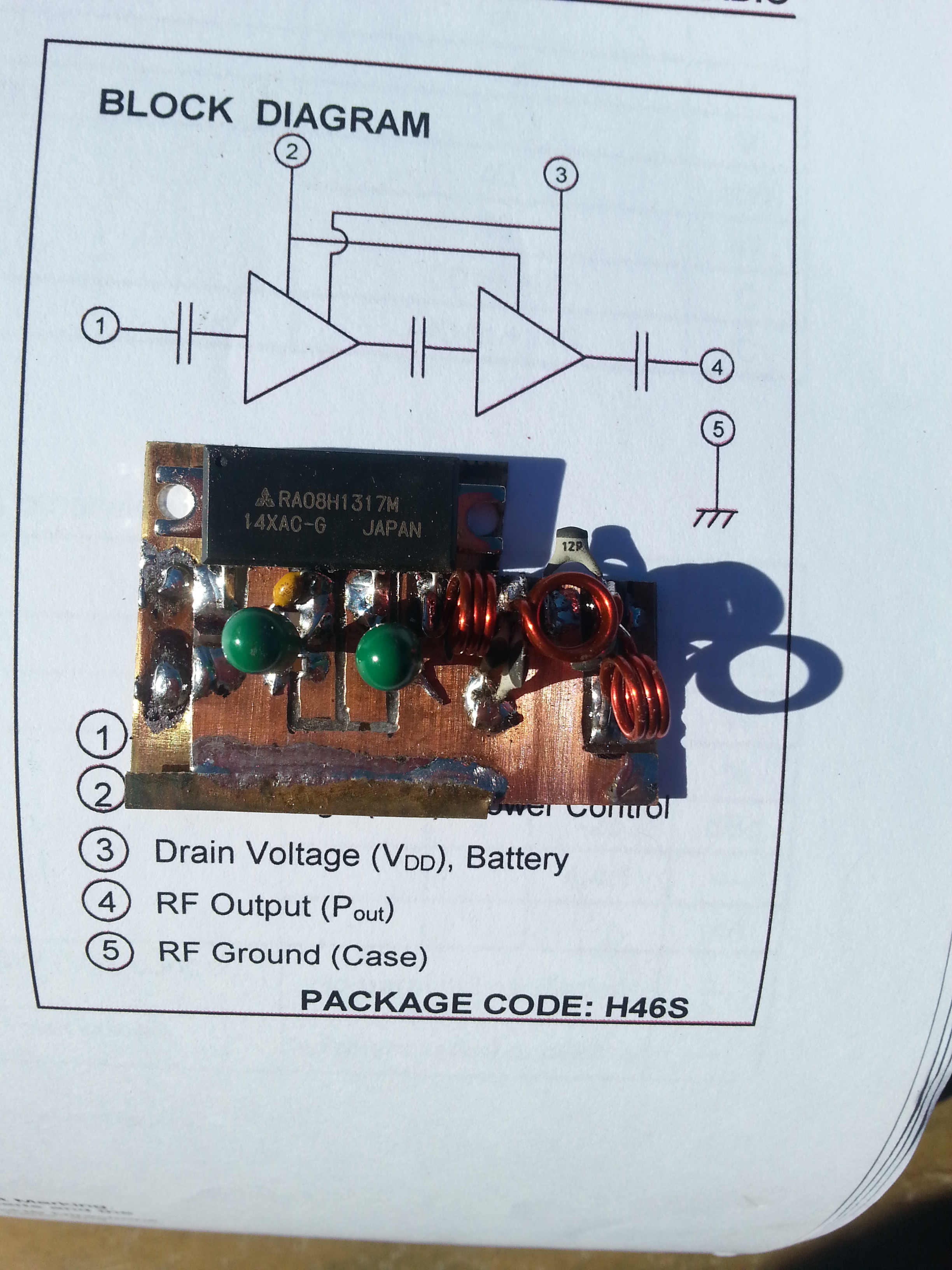
. The unit is biased from
class C to class AB1 by increasing the gate bias on the active devices
. A simple resistive divider from
a stable 5 volt supply to give 3.4 V at
1mA is all that is required . The small RF power amp is attached to a very large
heatsink to keep the electronics as heat stress free as possible , thus
cope with long overs and also the local club net on Wed evenings at 8
pm.. The RF output of the power brick is filtered by a five pole filter
to suppress the 2nd harmonic by 30
dBm and the third to greater than
46 dBm . .to keep
the radio inspectors from the door!!.
In the end I removed this from the tail of the power amp and placed It on
its own pc board very near to the RF output socket .
RF output filter swept response
The Finished transmit module before replacing upmixer driver board
The coax from the transmitter and receiver to the relevant coaxial bandpass band reject filters is 6mm corrugated 50 hardline which has absolutely no leakage as the shield is a solid but somewhat flexible copper tube.
The 10 W transmitter at 144.350 MHz is going to generate ônoise ô on the receive frequency of 144.950 MHz at a level of 100ĺs of uV at its RF spectrum output and you are relying on the High q filters to strip this 144.950 MHz noise from the receive frequency so it cant mask any weak signals on the receive input .
So it is very important that no unwanted ô144.950 MHz
noiseö leaks out of the transmit feeder connecting to the filters
and leaks into the receive
coax or receive antenna, thus appearing
on top of the weak uV wanted signal
.
You must use good quality dual
screened coax from at least the transmitter and receiver to their respective
filters to minimize this potential problem and
it is suggested you use dual screened coax also
for your coaxial filter quarter wave filter interconnections as well ( thanks to john
zl4rf for the coax)
. Read up all about this screening aspect
on Repeater builder .com on the Ĺweb.
In our
Branch33 repeater, we use separate vertically stacked
2* 5/8 co linear antennas about 3m apart and which
have a measured isolation of about 40 dB . These Hustler copies
give a low angle of radiation and a gain of approx 6 dBd each ,easy to
match ,tune , are robust and low maintenance.
A test was conducted where I fed 0.0 dB at 144.1 MHz from the N9310 Agilent signal generator into the antenna at my workshop in town, the antenna is a hustler copy of a 2* 5/8 in phase vertical collinear ( identical to the ones used at the linear site,) and, is about 6m above ground . I took my Agilent E4007B spectrum analyser to the linear site and plugged into the receive and transmit antennas . . I measured the received signal of ľ100.8 dBm on the lower antenna and -98.7 dBm on the upper antenna ůthis I guess this less the =12 db gain of the antennas and minus a few db for coax feed line loss , ??90 db?? represents path loss from my workshop antenna ?? I did bring up a handheld telescopic dipole too and when held vertical read ľ114 dBm on the analyser though it was at head height varied between ľ110 and ľ114 ůan interesting exercise .. reflections perhaps ??
When the repeater was installed I measured the minimum amount of signal to open the mute over the air using a signal from the signal generator in the workshop. The old repeater based on the tait 172 E band AM radio opened at ľ18 dBm into the antenna at the workshop.. The new repeater mute opened at a setting of -25 dBm approx 6 - 7 db improvement !!
The actual signal level to open the repeater mute on the bench was ľ124 dBm so given the path loss of approx 90.0 to 100 dB and the signal level into the workshop antenna of ľ25 dBm gives 95 ( midway ) plus 25 equals approx ľ120 dBm at the receiver,?? Im happy with that !!
When on the bench I set the receive osc and the transmit osc as close as I could to exactly 600 Khz split to minimise R.I.T use on SSB contacts . The HP8920A test set has a useful receive offset frequency readout function, on received carriers ,so I calibrated the HP8920A and the N9310 by using a GPS disciplined 10 MHz external reference oscillator to feed both instruments . The test of the signal generator output frequency locked to the same reference as the HP8920 on receive mode showed 000 kHz when both instruments were tuned to 144.350 MHz . . I connected the HP8920A on receive, to a small 2m antenna outside and the N9130 to the tall collinear and sent a signal at 144.950 Mhz, the test set showed an off set of 101 Hz on the translated signal from the repeaterů so far drift has not been too bad.
DC Power supply .
I have used extensive use of three terminal regulators in the various modules in both the receiver and transmitter, that minimises the changes in voltage of the 12v supply chain affecting biasing of stages, oscillation frequencies rf level of drivers etc, in all it makes for a more stable system. However being a solar site our battery voltage can potentially be from 12 to almost 15 volts and I had a small problem with the Mitsubishi RF power module in that is was recommended from maximum longevity not to exceed a supply input 12.6 Volts .Standard regulator circuits require at least 2-3 volts drop over the pass transistor be they three terminal or bipolar discrete to perform well ..This is too much voltage drop and I had to explore alternatives A lot of manufacturers produce low drop put three terminal regulators , they are much better than the standard integrated regulators but a lot of them have up to 1-2 volt drop at 3 amps or more some of course are lower than that it depends what you can get hold of ..I even tried a switch mode regulator but they still require a voltage drop !!
So search the net I did and found a very good article by Serge Patrishin, he is an Audiophile and designed a very good low drop out regulator based on a tl431 adjustable Zener controlling the gate voltage of a series fed power mosfet , The voltage drop across the mosfet is tens of millvolts at 2 Amps !! . just what I needed to give the repeater a constant voltage. Look here ů http://myelectrons.com/about/
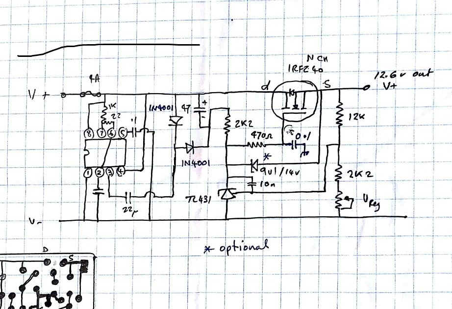
So simple but performs so well and subsequent looking on the net, showed lots of others copying and modifying Serges work ůincluding Me !! for the circuit to function you must generate a . 23 v positive supply to bias the mosfet gate and open the d-s conduction (I used a 555 in voltage double configuration) the tl431 monitors the regulated output voltage and adjusts voltage by robing the gate bias to control conduction hence regulate and it does it very well, just donĺt forget to connect the tl431 like a zener diode ie anode to negative and kathode to positive or it will not work.. believe me I know from bitter experience.
So far the repeater has been working well and I am
satisfied with its performance . You may well ask why build a linear repeater ?
Well it is an RF challenge to start with , something to get the brain going ..
The 20 yr old previous version,
which was burned by the psychiatrically disturbed one, was 16 Khz wide,
this version is 30 Khz wide, hopefully for better digital
rf fidelity .
NBFM contacts through a linear
repeater sound so much clearer than your standard FM repeater as there is no
Audio processing to distort and modify voice
. I can check deviation levels of remote transmitters over the air . I
can send calibrated deviated signal out over the air as well and know they will
arrive basicaly unaltered .. .We have been data/digital capable here in Rotorua for over 20
years !! we can take, p25,
dstar, dmr , AM, SSB , . it has multimode capability
. We donĺt need a pc at the site generating all sorts of digital noise
to interfere with our low background noise HF receiving site !
.That computer processing can all be
done at home at the users residence.
Hopefully multimode capability will stimulate more activity on the bands to everyoneĺs benefit