Frequency Demodulation assisted by Synchronous oscillator
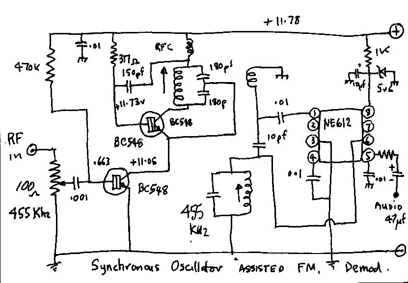
Circuit of Synchronous Oscillator with an FM demodulator
I have been meaning to try this for quite some time ,The idea is to use the S.O as the " amplifier " for FM modulated signals and to demodulate the Oscillator output to audio . I Built up the circuit above but added a quadrature demodulator based on a Gilbert cell mixer ie NE612 . The quad demod unit was driven from the S.O output . I had a simple circuit I drew up as above and etched up a double sided Printed Circuit and assembled it , it took me some time to get it to perform properly as I found i had made an error in the circuit diagram. I discovered more to my good fortune, more than design, an improved bias configuration that relates to the RF osc and the lower switching transistor . II managed to get the circuit performing very well ie lock at -100 dbm , When I measured the resistors id used I found I had a ridiculously low value (317 ohms ) biasing the RF and an equally high value ( 420K ohms) biasing the lower switching transistor .( cant read metal oxide resistors!) But it worked very well ! I connected the input of the S.O to the N9310A Signal generator set to 455 Khz and I took a 10 pf capacitive tap from the output link coupling that feeds the FM Quad demod circuit , and fed that to the input of the ESA4407 spectrum analyser set at 455 Khz and 200 Khz span . The Audio output of the quad demodulator was plugged into some amplified computer speakers so I could monitor the input signal . I set the Signal generator to 2.5 KHz deviation with an audio tone of 1.5 Khz
I measured the voltages around the circuit with a 220 Kohm
resistor in series with the positive probe of the DVM to minimise
the loading effect and provide some RF isolation .( this gives a slightly
lower real voltage that normal my real rail voltage was 12.04 v .
The Original S.O circuit was based on a capacitive tap on the
tuned circuit for feedback . I used a 455 Khz interstage transformer
and I decided I would use the RF out of the centre tap of the tuned
circuit to provide a feedback connection in the OSC circuit ,
Since I was having problems getting the circuit to function I rehashed the tap
system to a capacitive version in case that was responsible for the
malfunction ???? ( still not sure if it actually was) , I took a similar 455 IF can to bits removed the
capacitor and measured it , approx 125 Pf so that means I require
two 250 Pf capacitors in series, for a start , to be equivalent of this capacitance .
When the circuit was functioning I took some measurements of the performance . I fed signals at various levels into the synchronous oscillator and measured the S.O RF output on the spectrum analyser . Here are the results :
S.O out Level in dBm (modulated) Sig Gen level dBm lock range Khz ( no mod ) S.O out RF Level in dBm
- 50.7
-100
454.2---456.5
-48.9
-48.06
-90
451.5--459.6
-42.84
-48.01
-80
443.3---469.2
-42.79
--47.92
-70
420.8---506.2
-42.72
-47.72
-60
380.2---606.2
-42.49
-47.12
-50
321.0---541.0
-41.88
-43.23
-40
no wider but inter mod seen
-38.05
-40.24
-30
---------
-35.09
-35.65
-20
---------
-30.56
-33.13
-10
------------
-28.02
THE ABOVE WAS MEASURED WITH A 10 pF TAPPING CAPACITOR TO THE LINK COUPLING OUTPUT the dBm levels are NOT absolute but just a reading .
Lock range was achieved by sweeping the signal generator to extremes where the spectrum analyser showed loss of lock and the single carrier broke up and noise was heard from the FM demodulator .
Note the S.O RF output level at -100 dBm
excitation , The amplification of the SO is best seen
and heard with an stimulus FM signal , as if you use just straight
carrier ,all you will see is the S.O carrier lock solidly to the exciting
carrier . Hence I placed the FM Demodulator after it . It can be seen that
the RF output of the S.O increases with the increase in excitation from
the signal generator , this could be the summation of the S.O RF
output and the stimulating input signal , or it could be the wider
bandwidth low level FM sidebands being amplified as well .
The RF bias resistor was changed to 19 K ohms
and the modulated RF out put was measured from -80 dBm
up to -10 dbm input from the signal generator at 455 Khz
2.5 Khz deviation with 1.5 Khz modulation tone
-80 dBm
gave -24.12 dBm out and linearly to -25.6 dBm S.O.
output at -10dBm stimulating signal input . 70 db range and
approximately the same RF output level , I have yet to measure the more
important parameter signal to noise ratio at -80 dBm .
The measured RF output of the Synchronous Oscillator is only an
indication, not a true power measurement . The IF can in the
Oscillator was a 500 ohm output impedance one and the connection to the link
coupling of 10 PF was just to monitor the changes while varying the
input stimulus . this providing a large mismatch .
The S.O seems to be able to provide amplification particularly with
frequency modulated signals . I have yet to try it with real live 455 Khz NBFM
signals to hear what the demodulated audio sounds like on weak signals
.I am keen to see if the claim to digging signals from the noise has any
truth .. will it improve readibility ??
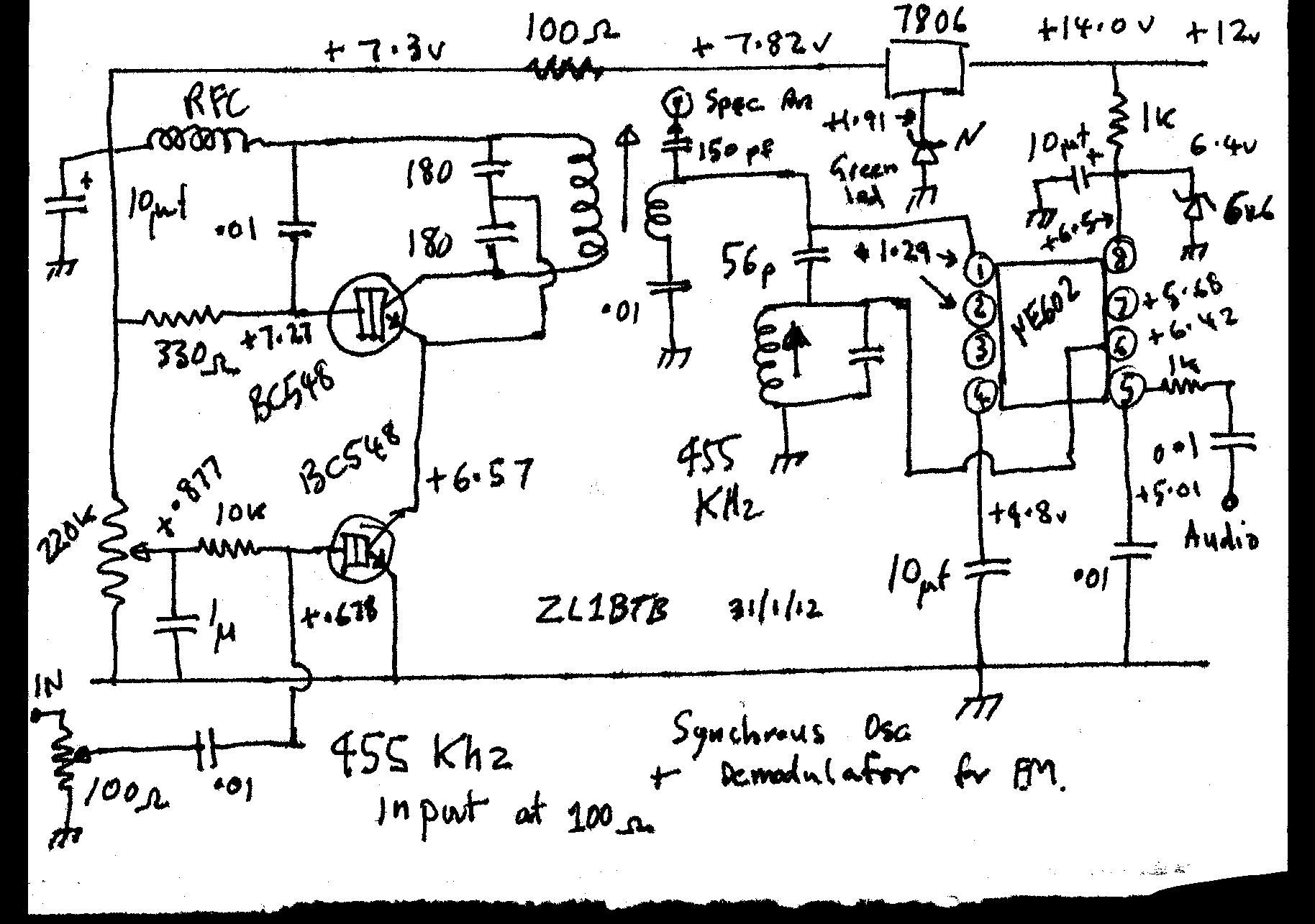
The Tuned circuit in the S.O used a split capacitor network with the feedback tap of the junction of the two 180 pf caps . I actually pulled a 455 Khz if can to pieces and extracted it with care ,, measured the capacitance in the agilent hand held capacitance meter and it was approx 120 Pf , if you try this circuit at 455Khz just crush the little dogbone capacitor under the tuned circuit with a sharp tool (as they are so fiddly to remove with out breaking the fine winding wires on the transformer ) .I did actually try connecting the feedback to the centre tap of the 455 IF can to see if the S. O would still work as well and for some reason not . I also tried the centre tap as the decoupled plus rail connection but i couldnt get S.O action perhaps in these cases if I played with the bias ???
Deviation synchronisation observation
Circuit has been modified again to see how I can screw as much performance as possible from it . The RF Feedback capacitor was increased to 1800pf , the V+ had a 1 K ohm resistor between osc and quad section , 1k bias resistor to RF transistor and a variable bias divider to feed bias to the lower injection transistor ..
Well have done some more experiments with this
circuit , and its hard to say if it does any better to enhance detection so far
. Comparing the Aor2001 scanner demodulating received signals , I took a 455 Khz
tap off the low level IF before demodulation to effect a comparison
. but ill have to use the sig/noise meter to quantify the results .
However I did evaluate the Synch L.O as a simple FM detector IF as its only two
transistors . I fed a signal into the circuit and looked at what can out of the
Synch Osc.
Output of signal generator feeding Synch Osc
output of Synch osc feeding quad demodulator and Spec an
-40 dBm input to Synch Osc -10dBm input
The Signal generator was set to 2.5 Khz deviation , with a modulation frequency of 1035 Hz . at 455 Khz , This showed the classic FM carrier null which I could use to see if there was any distortion of the locked frequency produced by the Synch Osc recovery, over a range from -83 to -10 dBm and by listening to the tone from the quad output , . There was no audible distortion or changes in its timbre , so it seemed to be consistant at most input levels . I listened to the a faithful copy of the input , the only aspect I'm not sure of the amount of signal feed through to the quadrature demodulator from the stimulating source at input high input levels as there is some "amplification " occurring note there is an output level change of -24 dBm output through to -17 dBm dBm output from -90 dBm in to -10 dBm in . it is well into limiting at -10dBm input ..there must be some feedthrough ???
Recovered Audio Observation
with the oscilloscope I measured the deviation sensitivity ,which is really a function of the quadrature detector , There is no loading resistor across the 455 Khz IF interstage coil so it recovers good audio on low deviation , 455 Khz @ 2.5 Khz deviation input yields around 56 mV of recovered audio , at 1 Khz modulation tone ... note there is no de-emphisis .
I have been using the AOR2001 Scanning receiver to tap of 455 Khz I.F as a signal source and by placing lots of attenuation in the antenna lead and listing to NBFM voice communications, have found that the Synch osc as a demodulator when compared to the MC3357 based IF strip, does have a slight edge on recovery of weak signals with poor S/N , You cant quite hear what they are saying out of the scanner speaker but you can understand voice on the Synch Osc , its still very noisy but readable , but the tuning of the S.O is very fiddly to enable this and I certainly would say its only slightly better . perhaps de emphasis application would help more to improve intelligibility ,more work needs to be done here , but its a simple IF strip to play with , I will try a simple single Fet transistor Quad demodulator circuit to see if I can simplify things more ..
Sweep Observation
The Spectrum analyser was set up for sweep operation using
the internal tracking generator . The tracking generator output was
attenuated through a 50 dB 50 ohm pad to bring the tracking output down
to the range -116 dBm to -50 dBm .Incremental low levels
of swept signal where passed thru the Synch Osc and the lock frequency width was
observed
-110dBm input almost 1.6 Khz lock range -100dBm input 3.7 Khz lock
- 80 dBm in and 35 Khz lock range -60 dBm and 500 Khz lock range
-50 dBm input and at maximum tracking range
Synchronous Osc and Amplitude modulation
I have tried the stimulation of the
synchronous oscillator with an amplitude modulated signal 90% at 455
Khz and noticed that when it is tuned exactly to the carrier frequency it
ignores all modulation and one hears no detectable demodulated audio from
the quadrature detector . This is a consistent observation within
a range of input amplitudes from -100 dbm through to -40 dBm where some AM
modulation appears to get through into the audio output , I suspect this
may be direct feed through of the AM stimulating signal from the signal
generator .
. However for this phenomenon to show , the S.O must be locked to
the carrier of the AM signal and not any of the sidebands .This is not a
simple operation and it is easy for the S.O to drift and lock on an AM
sideband . The signal generator is a single tone AM source and I have not
tried it on true audio modulated eg speech carriers to see if this AM
sideband suppression phenomena holds in that situation .
Addendum I have now tried the introduction of AM voice at 455 Khz into the Synch..Osc , I tuned to our local Airport automatic information service on 128.800 Mhz and listened to the output of the sync Osc - Quadrature demodulator and there is a solid lock of the system to the A.M carrier and the modulation is stripped from the regenerated carrier , I was quite surprised at how stable and "locked" it was , I could tune the L.O coil at least half a turn and the system remains in lock.. I am sure a lot of this AM rejection was contributed to the S.O action as seen by the spectrum analyser and not the nature of the Quadrature demodulator .
Output of signal generator 80% mod -80 dBm Output of synch Osc locked to AM carrier 80% modulation
Synchronous oscillator locked to a Submultiple of the output frequency
I can not see why a UHF
Synchronous oscillator cannot be locked to the oscillation of
a stable crystal controlled controlled Fundamental source ie a simple multiplier
situation . . This may be an easy and simple way of generating a quartz
crystal stable VHF-UHF oscillator without having to use the complications of
frequency multiplier stages ??
I have tried this experiment with the 455 KHz
Synch Osc I built and there was no problem locking it to the second , third and
fifth subharmonic of 455 KHz . however I did notice the spectrum analyser
display showed an awful lot of phase noise around the locked carrier ,
Perhaps I have to change the transistor bias configuration of both transistors
to improve the subharmonic locking operation .
click here to go back to the The Synchronous Oscillator
Vasil Uzunoglu designs and develops circuits and systems using synchronous oscillators for his company, Synchtrack (Gaithersburg, MD). He has an MSEE from the University of Missouri—Rolla and is a member of the IEEE. He has published numerous papers on synchronous oscillators and related circuits. Tech memo CL-38-81, Comsat Laboratories, Clarksburg, MD.