Fom Electronics and Wireless world ,September/October 1993, James A. Vincent, G1PVZ
The Synchronous Oscillator Designed by Vasil Uzunoglu
I found this article quite some time ago and was fascinated by its simplicity and the claims the article made as the what such a simple circuit can do . I suggest you read this Electronic Design Magazine article to get more technical information as to how the simple circuit achieves what it does.
http://www.edn.com/article/CA46326.html
Fom Electronics and Wireless world ,September/October 1993, James A. Vincent,
G1PVZ
The next paragraph is "stolen plagerised" from the EDN magazine But it sums the whole situation
"The popularity of PLLs does nothing to reduce the basic shortcomings and limitations that accompany such networks. PLLs are susceptible to noise that external signals carry and can acquire lock only if the SNR is greater than 3 dB. The input-signal sensitivity of a PLL is also poor; the PLL cannot detect input signals lower than –25 dBm.
An alternative network, the synchronous oscillator (SO), has many advantages over the PLL. The SO works reliably when the SNR is as low as –40 dB, and the SO can detect signals as low as –100 dBm. The SO is a universal multifunction network that can synchronize, track, amplify, improve the SNR by as much as 70 dB, and modulate and divide by rational integer numbers, such as 3÷4 and 7÷8, in one step With minor modifications, the SO can perform a variety of functions, including a PLL, clock and carrier recovery, a filter, an ADC, an audio/video-to-FM converter, a DAC, and and audio/video-to-direct-sequence-binary-phase-shift-keying/quadrature-phase-shift-keying converter.
The PLL has some particularly notable limitations. First, the loop filter must simultaneously satisfy the noise-rejection, tracking-range (same as data-bandwidth), and acquisition-time requirements. Unfortunately, the noise bandwidth and the tracking range are highly interdependent. Improving the noise rejection results in a reduced tracking range and an increased acquisition time. In other words, the product of the noise rejection and the tracking range is constant. Additionally, the acquisition time is highly dependent on the tracking range. The wider the tracking range, the faster the acquisition time. Any compromise between noise rejection and tracking range deteriorates the overall design.
Thus, the filter requirements for high noise rejection on one side and fast tracking and acquisition time on the other are contradictory. High noise rejection requires a narrow filter bandwidth, but a wide beta bandwidth and fast acquisition time require wide filter bandwidth. The loop filter simply cannot handle these contradictory requirements simultaneously. Designers can rarely meet all of the design requirements, and the result is a poor design after making the necessary compromises. Temporary solutions, such as widening the tracking range by sweeping the entire data bandwidth during acquisition, require additional equipment and introduce additional problems."
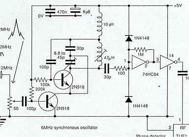
Above is the circuit of a 6 Mhz version off the web, it will give you a good idea or component values to start with , try it out you will be impressed!!
I built the circuit up using a couple of BC108 transistors and a tuned
circuit from 1.5Mhz ( LO can from a transistor radio ) There were no
component values given in the article ( they used 140 MHz ) so i used the ol
experience rule of thumb ,take a guess at component values and try it out .
apply power ( current limit set to 50mA and hit the "on"
switch). after a bit of component juggling ,mainly the single bias
resistors, I got relatively clean oscillations as shown on the spectrum analyser
at around 1.45 MHz
I connected the signal generator to the ext RF input circuit of the S.O
and punched in 1.350Mhz, I then incremented the RF output level from -124 dBm in
10dB steps while watching the Analyser screen to see what was happening
, This oscillator would lock to the incoming signal at -74 dBm
!! you could see the interaction of the two frequencies as sidebands
appearing either side of the unlocked SO carrier. As the level of the external
carrier rose, the mixing sidebands increased and if the frequencies where close
enough, given the injection amplitude , bingo you would get lock !! The
sidebands disappeared and there was locked carrier , this was evident by
tuning the signal generator back and forward and the S.O mirrored the frequency
excursion exactly.
You could see this phenomenon on the frequency counter as well ,it was rock
solid and in full agreement with the digital display on the HP signal
generator. At -54 dBm, the excursion was quite a few hundred KHz
before lock was lost. The greater the injection amplitude, the wider the
lock range .
This cobbled together oscillator would also lock to a stimulus signal of
-100 dBm !! the lock range how ever was a few tens of KHz ,but never the less it
was locked !!
Want to lock a 1296 MHz osc to a crystal , use the S.O principle, you
could multiply up from a crystal Osc with a minimum of multiplying stages
and just tune up the harmonic you want to lock to , and even if its only -30 dBm
, the S.O at 1296MHz will lock to it !!
I tried FM modulating the injection signal and fed that into the S.O . The RF output from the S.O tank circuit was coupled ( split) to the spec an E4403B and through 60 db of attenuation and into an AOR3000A receiver tuned to 1.350 KHz to hear what is going on (ears are very good analysis instruments ). Tracking the injected FM signal was not a problem and the S.O did a great job of regeneration of the weak signal and it would regenerate the signal over very wide deviations , much wider than voice comms/music would use . This leads me to my next experiment ( yet to try ) How will the S.O handle digging modulated signals out of the noise , ie can it pull out a modulated signal buried in the noise ? and to what low level of S/N will it allow us to copy a NBFM signal ?? Will it be better than a Quad detector or PLL Demod?? Because of the good level of RF output of the S.O there is no reason why it cannot feed directly into a DBM configured as a Quadrature demodulator for FM detection ? ( I am cheating a bit by using the AOR3000 to do this for me .)
I next tried switching the Signal Generator HP8640B to AM output, First
I connected the signal generator output to the Spec An to see the modulation
sidebands at 100% carrier modulation , This showed the usual sidebands 6 dB
below the carrier as one would expect . I then reconnected the S.O output to the
spec An and AOR3000 and injected a low level -70 dBm signal into the
S.O , Lock was not a problem as I expected, but the A.M sidebands where a
long way down on the carrier, greater than 30 dB below and if one carefully
tuned the injection signal as close to the free running S.O frequency ,the A.M
sidebands almost disappeared.
I wonder if the S.O could be used to lock onto the carrier of an A.M
signal and its locked output be used as the un-modulated carrier to
inject into a mixer to perform synchronous demodulation of AM ??? .
I will next build an oscillator at VHF and see how that performs
REFERENCE
Vasil Uzunoglu designs and develops circuits and systems using synchronous oscillators for his company, Synchtrack (Gaithersburg, MD). He has an MSEE from the University of Missouri—Rolla and is a member of the IEEE. He has published numerous papers on synchronous oscillators and related circuits. Tech memo CL-38-81, Comsat Laboratories, Clarksburg, MD.