DSBSC demodulation by
the squaring loop technique
There are a lot of small simple DSB transmitter projects
on the air , these are usually low power transmitters of 1 to 10 watts ,they are
easy to make and also efficient on power as no wasteful RF carrier is sent along
with the information sidebands.
The usual way that most radio amateurs demodulate double sideband
suppressed carrier signals is by means of a single sideband receiver ,
thus using upper or lower side band mode then zero beat the DSB
signal for best intelligibility;
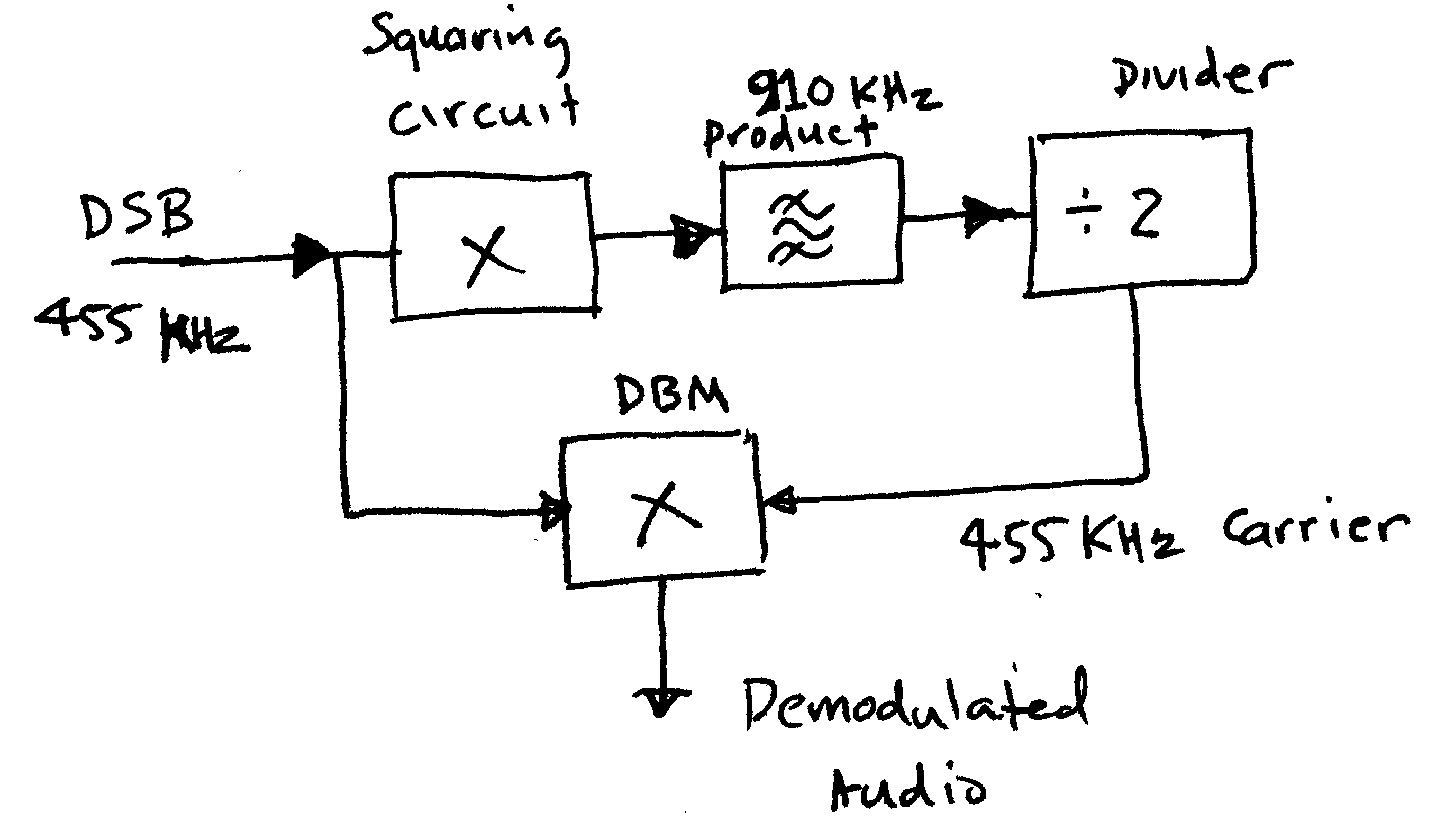
The the other way to truly demodulate dsbsc that I know of and have seen
circuitry and theory is by two techniques, 1, the squaring loop
or 2. Costas loop . either technique to synthesise the bfo carrier from the upper and
lower sidebands and enable efficient demodulation using both upper
and lower sideband simultaneously in a product detector or mixer. .
This is an experiment to test this first method and to examine the function of the
components of the squaring loop . My experiment was started at 455 Khz
and the main reason I picked this common frequency was its universal use in
radio receivers and my signal source , the HP8904A will
only go to 600 Khz ! it is a versatile synthesised source that can perform many
types and mixes of modulation function ,AM,FM,PM,Noise,and Double sideband
suppressed carrier to name a few . so there is my modulated
DSB generator on hand . To demodulate DSB you must reinsert the carrier
synchronously with the two sidebands to get the speech to sound natural . This
fact is the saving grace that enables the demodulation of the dual
sideband suppressed carrier
signal and enables one to derive the correct carrier ( b.f.o) relationship
to the DSB signal . THE CARRIER frequency IS ALWAYS MIDWAY BETWEEN THE UPPER AND
LOWER SIDEBANDS , Just imagine a 1 Khz modulation tone , the transmitted
signals are carrier frequency ( remember its missing) plus 1 Khz and
minus 1 Khz these are the frequencies of the two transmitted signals above
and below the suppressed carrier , so all we have to do is some
electronic manipulation of these two sideband signals and we
can derive the original suppressed carrier frequency. midway between them .
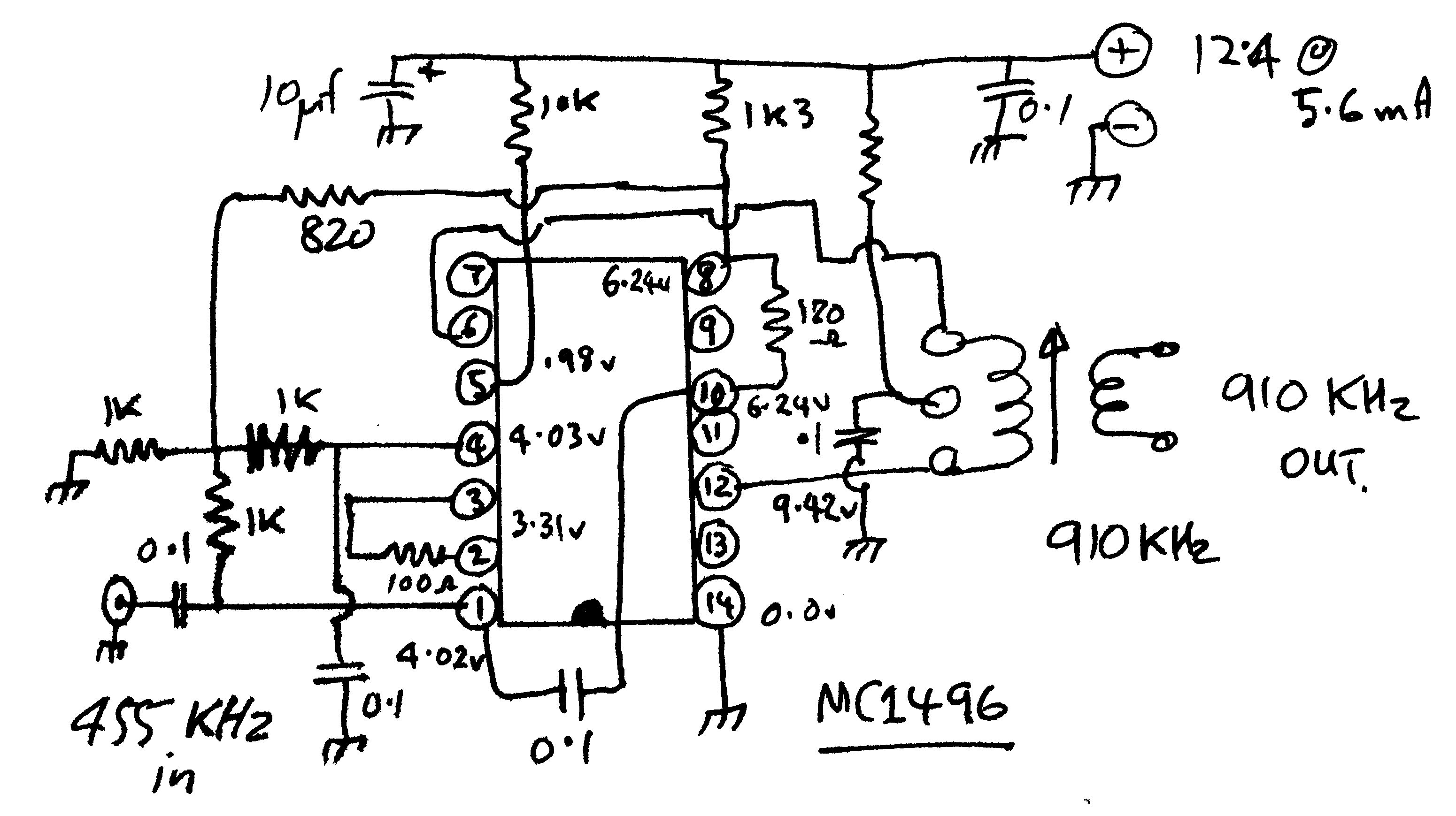
MC1496 configured
as a doubling circuit I found an increase in the wanted output if the
value of the coupling capacitor feeding pin 10 was 1/5 of the input cap value
Enter the Squaring circuit,
There are several configurations to achieve this I decided I'd use a MC1496 mixer as a suitable squaring
circuit ,its got lots of gain ,they work well, also hoping the carrier
suppression features of the IC will minimise the feed through of the 455KHz DSB
to the output of the squaring circuit and we will only have 910 KHz to contend
with .
For any DBM to act as a doubler or squaring circuit you feed the same
signal into both input ports ie the carrier port and the signal port and
the product will appear at the output .I set up the signal generator at 100mV,
feeding the two input ports and spectrum analyser to look at the output of the
mc1496 wired in the doubling mode as per the IC data sheet ' I
also ran mine on a one sided 12 volt rail ( no dual volt source) I used
the recommended component values in the MC1496 applications Note, downloaded from
the web .
I'm not going to get into the math of this process ,
suffice to say there is plenty of that on the net if you look around ( but
no circuits of how you do it practically) hence the project , There are a couple
of excellent articles on DSB demodulation out of the now extinct HAM
RADIO magazine . and my experiment is based on the one using the squaring
loop technique , In the Article by ..H Priebe Auto
product detection of DSB,........HAM RADIO March
1980 he uses a Fet transistor
biased into square-law ( non linear) to multiply the 455 KHz DSB signal
by itself and derive the wanted product s. It turns out
if you take a 455 KHz DSB signal and square it ( multiply it by itself ) you get
some useful signals out .. By doubling the 454Khz and 456Khz sidebands, you
will get 908 KHz and 912 KHz out of your squaring circuit , that
is as we mentally visualize the product of the "times itself"
operation will produce BUT, there is a third product of interest, the single
product 910Khz!! divide this by two and the result is 455 KHz ! midway
between the upper and lower sideband . feed this into our product detector
as the BFO and voila out pops 1 KHz tone exactly what we
want . So there it is , the DSBSC squaring loop in a nutshell ! easy
huh ! but do you think I can find additional practical circuit on the net
to build one ....no ! a Good place to start when you are
researching projects is to do a patent search on the topic , all sorts
of stuff turns up that will assist in your understanding of the idea but
don't get distracted when doing patent searches, there is so much curious
and interesting stuff out there ,its easy to get waylaid .
I was somewhat dismayed at the low conversion efficiency
of theMC1496 circuit as a doubler ,at the input powers I was using , there
was quite an amount of loss in the squaring process. however when I
tried an SBL-1 as a squaring circuit it just would not work at the low levels of
power one would expect from a radio receiver I.F so I guess the 1496 is not so
bad after all .
( today found another simple doubling circuit to try using just 3
transistors)
I fed 912.4 KHz into the squaring board input and looked at the level of
912.4 KHz at the output , it was -55 dBm . a fundamental suppression of 35
dB . note this signal is going into both carrier and Rf ports so I
dont expect to get the usual 50-65 db rejection of signals one would get
with the MC1496 configured as a mixer .
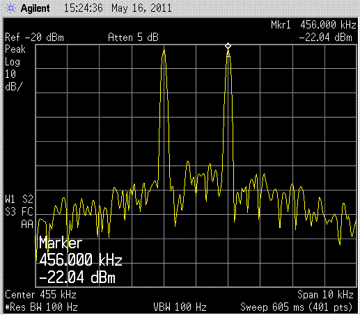
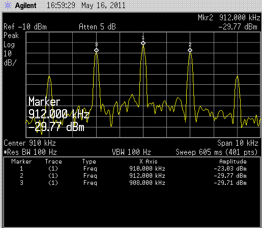
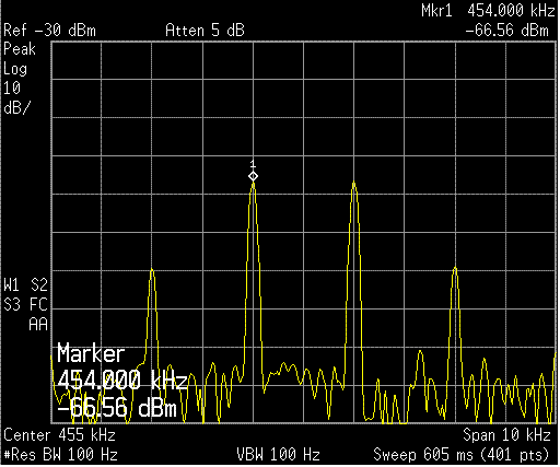
100 mV DSB at
455 KHz 1 KHz Mod into MC1496 -22
dBm
Output of MC1496 note 910 Khz carrier generated sidebands at 2
KHz !
F
The wanted product at 910 KHz is about 6 dB above the
other products , this 910Khz frequency will have to be selected or filtered
to isolate it from the other sideband ( note they are twice the original
sideband frequency from the new carrier ie 2 KHz ! . a single series
quartz crystal at 910 Khz is what the HAM RADIO article used to pass the 910 Khz
. this is where the project gets very expensive , custom made crystals are not cheap
,I will try and obtain one to duplicate the original article . (
subsequently gave up on this idea they are too expensive , so I changed
IF frequency )
(The only reason I was keen on 910 Khz meant I could easily
use the 455KHz output of my Icom r75 receiver with fiddling or additional
mixing )
There
is of course no reason why one couldn't in practical terms use
for example a 9 Mhz i.f and then for a filter , an 18 Mhz
microprocessor crystal, readily obtainable inexpensively from Mouser.,
Radio Spares , Element 14 , or many other component suppliers .
or use a completely different IF that suits the filter crystal you have ???
I
did some tests ramping the 455 KHz DSB signal up and down from 1 mV input to 200
mV and saw the 910KHz wanted product was always at least 6 db above all the
sidebands ..Im looking at the 910 KHz output spectrum and thinking "that now looks like an
AM carrier signal ?", the wanted product is 6-7 db above all the rest of the
carriers so what if I pass it through a limiter like an FM radio does and
hopefully the capture effect will hold the 910 Khz and strip the unwanted
carriers . I tried the FM IF limiting and there was some
increase in carrier level above the existing sidebands but i figured it
was much too complicated for the amount of extra carrier level
derived plus the generated intermod from limiting so I gave it away
,
Feed through of 455Khz at doubler output -66.5 dBm
What i did notice was the output conversion of the
squaring circuit using the mc1496 is not good ie a -24 dBm
input at 910 Khz gave a product 1.843 MHz @ -36 dBm also
if there is a 10 db change in input level there will be a
corresponding 20 db change in output level ie drop the input to the
doubler by 10dB and the wanted "doubled carrier product" falls by 20 dB
!! following the square law !!
FILTERS :
Back to filtering techniques to prise the wanted synthesised carrier
out of the squaring circuit. I have been playing around with simple single
quartz crystals .as band-pass filters , I experimented with phasing
crystal filters with the moveable passband rejection notch but came to the
conclusion that the rejection notch is not required in this application . the
single phasing crystal did work but the circuit was a little fiddly ,so I
looked at other filter ideas .
Just a
note : When sweeping very narrow high Q filter circuits you must sweep at very
low rates, I was getting a strange ringing on the high side of the pass-band
,these looked like ripples on the trace , I fiddled for ages with components
trying to determine what was causing it only to realise that it was due to the
excessive sweep rate of the Agilent E4407 spectrum analyser in tracking
mode . Just because these newfangled machines have an auto function that mixes
and matches sweep speed to resolution bandwidth and sweep width it can
still get it wrong ! . beware and be prepared to override auto settings if
things just don't look right ......... you can never sweep too slowly but
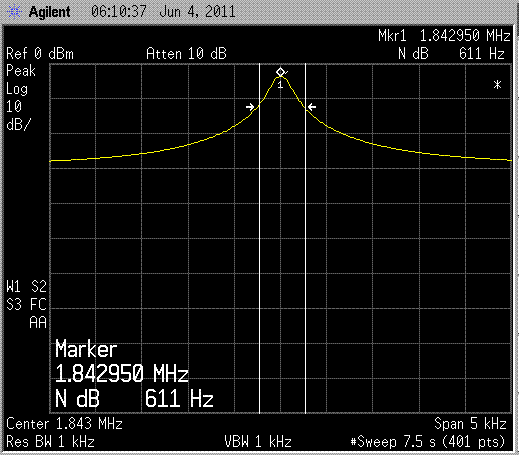
you can sweep too fast !! ..I experimented with a number of HC49 crystals
, 10 Mhz, 4 MHz and 1.8430 MHz , sweeping them to see which one gave the
narrowest response and as you would expect the 1.8 Mhz was the winner !
typically 250 Hz but often less , this gives me -3dB
selectivity 125 Hz away from the wanted carrier and since voice comms tends to
start above 300 Hz this amount of roll-off from the simple single crystal should
give a good usable wanted carrier to unwanted sidebands Ratio
; Amplify this filtered carrier up to a level where it will
trigger a divide by two counter and then I have my regenerated carrier at the
correct frequency for injection into the product detector to recover the
audio from the received DSB . well that is what I imagined
anyway!!
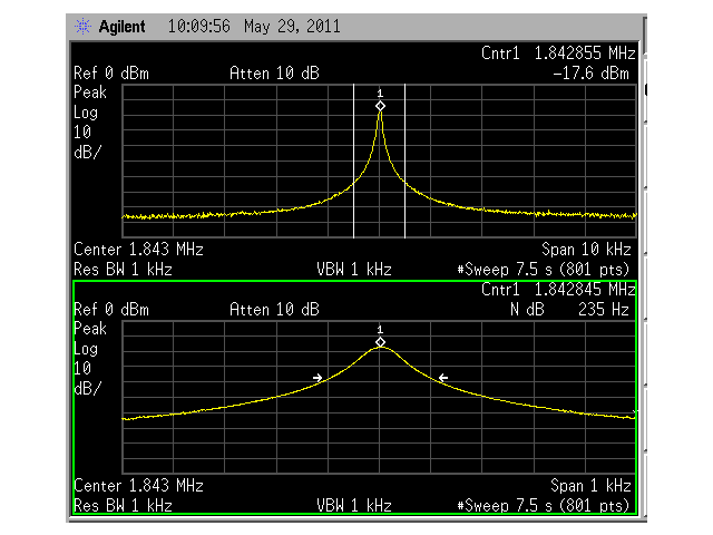
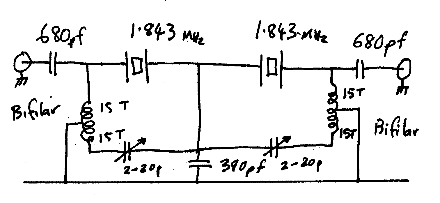
1.84 MHz crystal filter swept response
1.8 MHz microprocessor xtals see
LA8AK website for more details
To test the concept I had to put together a simple DSB generator at
1.843 Mhz .The 1000 Hz audio from the HP8904A into an SBL-1 DBM , 921.523 Khz
( half of 1.84304 MHz) from the from the Agilent N9310A Signal
generator
and the resulting DSB output into the MC1496 squaring circuit with the 1.84304MHz
crystal as a series filter on the "product " output port . I did several
audio modulation frequencies to see how the sidebands showed in relation
to the carrier , and the wanted synthesised carrier was always much higher than the
sidebands .I originally tried the classical simple single
phasing crystal filter circuit , a la 1930 radio techniques but the
poor shape factor allowed a lot of unwanted sideband energy either side of
the wanted derived carrier , even though the wanted carrier was 15-20 dB
above the crud I felt we could do better ! when I get things operational i
can fiddle to see how much minimal carrier we can get away with and the
demodulator still function , Extensive searching on the web
brought me to LA8AK web pages "
Improved stopband of crystal ladder filters " I replicated one of his
circuits with some changes in component values, scaling with frequency ,
the response of this simple filter is exceptional , look at the
swept response in the Dual Window above , note the 10 Khz span and the 1 Khz span
. This LA8AK website filter has stopbands up to 80-90 dB below the minimum
bandwidth .
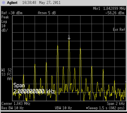
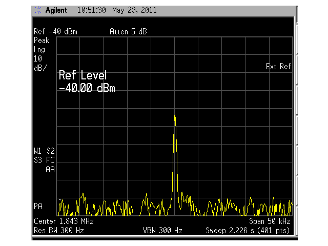
100 Hz modulation at 921.523 Khz +/- 1
Khz ( squaring output )
Filtered carrier derived from
MC1496 squaring circuit (300-3K modulation)
The squared output signal was fed through the
LA8AK website dual crystal filter and viewed on the
analyser see filtered signal above, The Fixed audio frequency tests where very satisfying but
how would it go with real comms quality speech?? so I then decided to use a local Govnt agency comms channel
as my speech source ( Automated continuous speech from local airport
on weather conditions)
as an audio feed into the DSB modulator. I was interested to see the
processed RF spectrum from the squaring circuit after it had passed
through the new series twin crystal filter . I took the audio output of my trusty old Yeasu VX-5 and fed it into the audio port of the sbl-1 DBM
. ,
At no time was the wanted carrier ever approached in significant levels by the
sidebands
around it , see filtered carrier picture
You will notice the losses of the very narrow dual crystal filter is quite high
,
around 17 dB , these loss appears to be consistent with these extremely narrow crystal
filters (although maybe my poor matching is the source of the great loss??) . A much wider filter, 3KHz or so will have much less loss , maybe
a couple of dB or so . But that's not a problem as the DSBSC demodulator will
sit at the end of the receiver IF chain, mollycoddled by the AGC and be supplied with plenty
of RF level and a good signal to noise ratio to work
with .

Modified novel cascade if amp off Harry 'SM0VPO web page
on IF amps , NOTE: the ZL1BTB MODIFICATION replacing one
of the decoupling
capacitors with a crystal on the frequency I wish to
enhance
There is still a large amount of amplification to bring
the derived carrier up to a suitable useful level , I tried a CA3089 FM
IF
strip but was not happy with the broadband noise coming from the limiter ,the
output never looked clean on the scope , So I looked through the web
( as one does) looking for suitable circuit when I came across this one in Harry
SM0VPO website ,it is a cascode almost totem pole amplifier
configuration where the first three transistors are in series . I built up the
circuit on double sided PC board . I swept it on the spectrum Analyser in
tracking mode and man has this circuit got some low frequency gain! 80 dB
plus , see the screen shot , The tracking generator out (amptd was -60 dB) with
30 dB in series with that !! ( I had to reduce the tracking generator RF output
to almost 90dBm with external pads to stop the cascode amplifier from limiting at the output ) ,
it has your typical ultra high gain broad band roll off . BUT it is a
useful circuit, To cut down on the broadband noise , I replaced one of the
1nf emitter decoupling capacitors with a microprocessor crystal at 1.8430
MHz and obtained a very useful response , I have marked the 10dB
bandwidth points as I wish to see how it performs filtering out noise on the
multiplied sidebands ,note this simple single crystal filter has poor
stopband attenuation ,but I only want my wanted signal 15-20 db above the crud
to use it , I connected the oscilloscope probe to the series amp output and . the scope pattern looked
a clean sine wave , I suspect we can get
some good clean logic level triggering of the following divide by two
with this output !
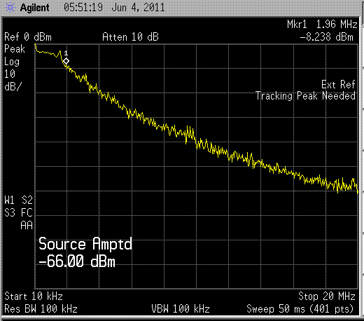
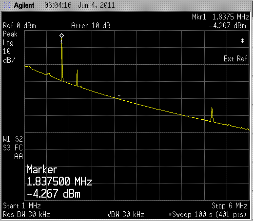
Harry's cascode IF strip wide open .....terminated
in 1K at each end
Emitter bypass cap now replaced with 1.837 MHz crystal
This filter has much less loss as the twin xtal
filter. I suspect this is all I require
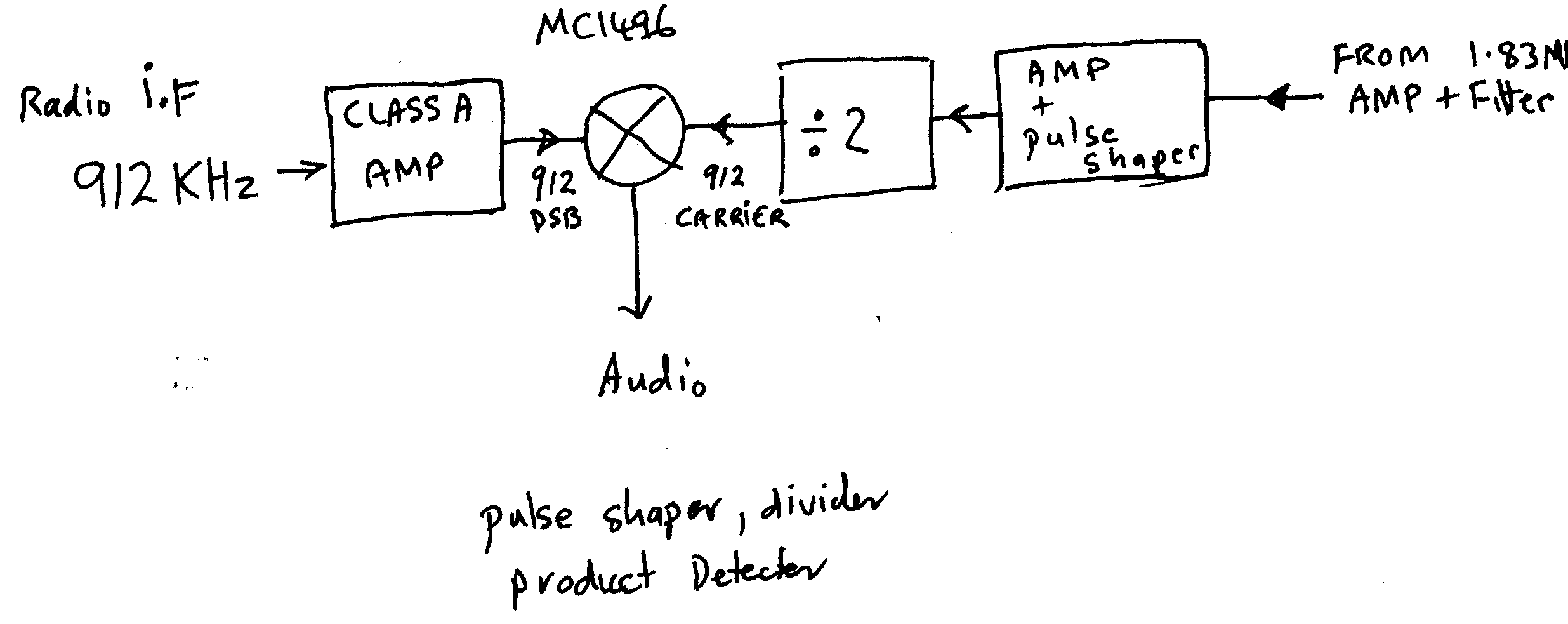
block diagram of the tail end !
I have four 1.843 Mhz crystals hence the different
centre frequencies on display
The level of filtered carrier is quite low and around the 20-25 uV level. It
will need a good deal of amplification to bring it up to a level where is can
reliably trigger a "divide by two" to generate the BFO injection frequency
. ,
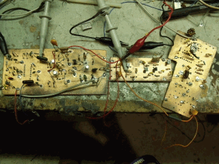
I made up the above SM0VPO cascode amplifier
with the ZL1BTB crystal modification to narrow the bandwidth and
remove excessive broadband noise . I built this on double sided PC board
to minimise potential interaction and to maximise screening , the output of the
squaring circuit was connected to the high gain narrow band amplifier , I
connected the Oscilloscope to the output of this amplifier and feed
varying levels at 1.83 Mhz into the SM0VPO amp from the
signal generator and noted the high gain output (terminated in 1 K )
amplitude . -60dBm input gave 12v pk to pk . -63dBm 11 v
, -66dBm gave 6,5v , -70dBm gave 2.8v
and -80 dBm gave 300 mV, however , a noisy display .
I suspect with the average IF level of most
receivers being up near the -20 dbm level at the end of the I.F so
there will be plenty of signal and lee way for the circuit to operate over a
moderate range of I.F outputs,
I then built up the second half of the H Priebe Auto
product detection of DSB,........HAM RADIO March
1980 circuitry once again on double side PC board , This contains a
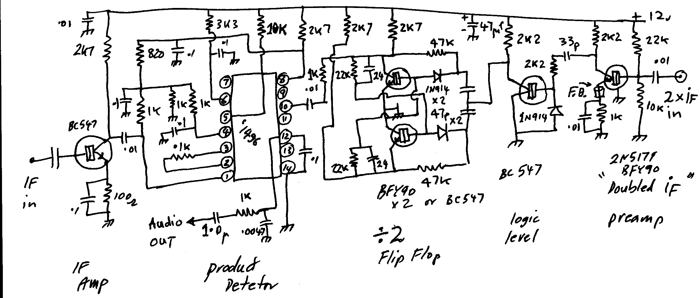
1.84 MHz class A broadband amplifier, logic level pulse shaper ,
transistor cross coupled multivibrator as a divide by two , a class A 920
KHz IF amp and a mc1496 product detector with audio output .
I have the most trouble with the divide by 2 circuit and if I was going down
this road again I would use a dedicated CD4013 cmos logic I.C. , I had to change
the component values quite markedly from the original to get the circuit to play
ball..... so frustrating for such a straight forward
circuit . !
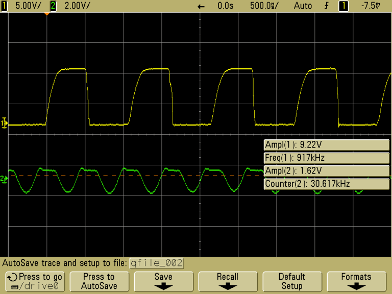
-100 dBm into the series Amp board and
digital divider board
just a note there is an error in the circuit of the divide
by 2 module , the two emitters connect together and to earth ,
but not as shown in the diagram, sorry my mistake
To test thes sensitivity of just the "flip flop" board I
connected the Agilent N9310A Signal generator to the
input at the "doubled IF Preamp" and the oscilloscope probe on the
pin 10 of the MC1496 . I set the signal generator to 1.8248 Mhz and
ramped the output amplitude up and down , the minimum level I could get reliable
toggling was -- 33dBm .
I connected the two pc boards together . fed the
1.84MHz from the signal generator into the series Amp , placed the scope probes
one on pin 10 of the MC1496 product detector and the second probe on the
collector of the double if preamp transistor .I ramped up the amplitude of the
signal generator from -127 dBm and watched the scope traces,
At weaker than -100 dBm I could easily get reliable solid half frequency square waves on pin
10 ! . Any way after getting it all operational, I decide to test
it . The 1 Khz DSB out of the SRA-1 DBM ( I suspect my
original SBL-1 was dodgy) was resistively split in two, Half feed to the I.F
input of the product detector and the other half was fed to the input to the
squaring circuit , it was all connected up and the Rf
level from the signal generator set to show good clean square waves coming
from the divide by two ,on the scope and I listened to the audio output of
the product detector and there was the 1 Khz audio tone (as
generated by the HP8904A feeding the I.F port of the SRA-1 DSB generator )
so the concept works though its somewhat "complicated" .. The next real test is to pull some real dsb off the
air on HF and feed that into the demodulator and see what it sounds
like !!
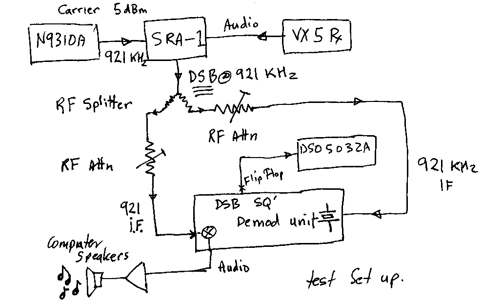
When running the DSB demod board with communication audio coming from the vx5 ,
it was amazing to watch the square waves from the divider on the oscillioscope
appear in time and solidly locked , along with the audible speech
coming from the amplified computer speakers , I was able to simulate varying the
I.F signal levels with the switched attenuator feeding the
squaring input .. when the signal level dipped below trigger threshold the
audio was stilted or muted .
...
What I did note that was somewhat amusing , I could twiddle the
signal generator frequency backwards and forwards from 921.4857 KHz to
921.4257 KHz rapidly and the audio didnt change in pitch at all !! so
stability is not so stringent as SSB ( figures really when you think
how the circuit actually works ) .. beyond that range of
frequencies there was some distortion appearing but Im sure that was due to the
divider stage being starved of signal as the passband of the crystal filter
reduced the level of synthesised carrier .
Things to try yet to try MC1590 as squaring circuit ,
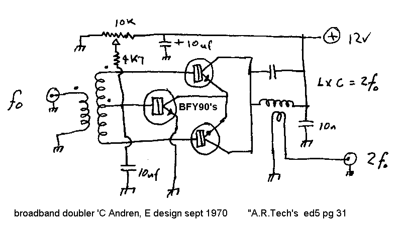
and newly found 3
transistor doubler out of RSGB "Amateur radio techniques"
I made up the "Andren " broadband doubler up on some double sided PCB
but I modified the circuit slightly , a tuned output with link coupling for low
impedance out and a small modification to adjust the bias and see what it
did to performance , I used BFY90 transistor because I have a couple of
dozen or so ..
, I noticed the original circuit had a fixed 5 K bias resistor , I found this
was too much for the BFY90's, they all turned on too hard and got
hot and bothered so I changed to an adjustable bias which I set to just
below for maximum signal out (0,813 V on the base of the
BFY90's ) These are the results of the experiment as a
doubling circuit ,I used 4.17 Mhz input and looked at 8.34 output
( only because the hand 120 Pf cap I found on the bench and the toroid I
had in the output circuit resonated at that frequency ).
input -25 dBm
out -13 dBm
-35
-28
-45
-41
-55
-53
-61
-59
-63
-61
-66
-65
Well this little circuit performs very well for what
I require! The MC1496 was -24 dBm in
and -36 dbm out ,( -12
db conversion ) this little circuit is
-25 dBm in and -13
dBm out !!! (+12 dB conversion
) The next test will try a link coupling to the input to see if matching
improves the performance now I have to try it with DSB and see how
it goes producing the frequency product I require ..
This is the circuit Ill try on the front of my filter/divider board
combination . with all these little improvements here and there I may be able to
reduce the complexity of the demodulator and the overall required gain
hence improve the stability of the whole circuit ...
I may even try just the divider board on its own connected to this Andren
doubler circuit, as the divider board will trigger reliably at -33 dBm
but I will use a 1.83 MHz crystal to replace the emitter bypass capacitor
in the "doubled IF Preamp" part of the divider circuit ...watch this
space...
more to come
Once it is all operational I will try to measure the
minimum signal required at each stage to make the circuit work,( done this) Im
sure the whole circuit can be greatly simplified , ie a mc1590 in mixer
configuration , could replace the MC1496 squaring circuit and thus have extra
gain before passing into a more simple high gain IF amp of maybe just two
transistors with emitter bypass crystal , the "divide by two" would
be a CD013 and the product detector could be a simple dual gate mosfet
configuration ??
perhaps one could incorporate a dedicated NBFM receiver
chip mMC3362??? etc as they have most of the circuitry we require .
you can see the simple ssb product detector
using only one sideband is attractive BUT the tuning has to be spot on and
no drift of the receiver VFO .However with this circuit , drift is
not so much a problem ,so long as you can get signal through the "doubled IF"
crystal filter at an amplitude sufficient to enable the divider to work
,then drift wont cause audio distortion .. .
Double sideband demodulator mk3 squaring loop
DSSC demodulation by the
squaring means diode doubler technique
.watch this space more to come .
Double Sideband
suppressed carrier Demodulation Patents
These are all the References I can find on Double sideband
suppressed carrier demodulation , there are bound to be more , they are
all US patent Office registration No.. The E ones are European
Patent office ,
Have a look on the application of File dates and the Granting dates and some
people had to wait a long time before their patents were granted .
2924706 ,2992326, 2999155, 3047659, 3060383,
3088069, 3108158, 3141066, 3151217, 3252094, 3286183, 3345571, 3457513,
3537017, 3593149, 4253066
4821322, 4475218, 4642573, 4862098,
2979611,2397961, 4130839, 4430620, 4485487, 4510467, EP0291826B1, EP0293828B1,
2193801, 2276863, 2784311,
3375453 , 3430151,
3719903, a novel dsb modulator ,
back to home page


