Well there are several types for sale on the web , so I bought a sample of each and played with them on the RF bench for use as RF preamps for ham radio applications
They
all make the usual outrageous claims but I suspect some attributes of
them may be useful in different situations , I have measured gain,
input and output SWR using and E5061 300Khz to 3 GHz VNA and Noise
Figure with an HP8970B with the internal 2045 Mhz option and
N8972A Noise figure meter with 1500 Mhz Limit . I have gathered
several noise sources, a Noise com NC346 ~15 dB ENR which has had
an additional calibration at some time in the past (new sticker
over the original) a cheapy chinese sold in USA ? Off the
internet calibrated from 10 to 1800 Mhz ~`15 dB ENR and a “6”
dB ENR RF2035 from G8FEK.com, calibrated from 10 Mhz to 3.3GHz also from the internet,
but made in England and that comes with a calibration certificate as well, a much better manufacture and a website to back its pedigree . If you cant afford a .1 – to 18 GHz real one go for the RF2035 noise source they just seem so much better all
round .
Noise figure measurement is fraught with pitfalls
Firstly the accuracy is mostly dependant on the accurate calibration of the Noise Source . A good commercial noise source is quite expensive.. New US$2000 plus , but you can get good second hand ones on the market . Most expensive noise sources hold their calibration for a long time although it is recommended they are recalibrated yearly $$ . The Usual branded ones by HP.. Agilent.. Noisecom and Eaton et el .. are usually calibrated to two decimal places after the decimal point . eg 15.25 dB ENR and its not a cheap process to achieve this against a special accurate ENR standards.
The cheaper models are usually calibrated only to one place after the decimal place eg 15.2 dB ENR …. Accuracy is reflected in the price..
Noise figure meters calculate the gain and noise figure of DUT,s using the difference between the thermal noise level generated by 50 Ohms resistance at e.g. room temperature and the artificial hot noise source of a calibrated noise generating semiconductor diode . Some sources are 15 dB ENR for moderate to high noise figure preamps and some are 5-6 dB ENR used for low to very low noise rf preamps.
Because of the comparison of noise levels , you must set the actual ambient room temperature in Kelvin, into the instrument before calibration ,so it can calculate the room temperature noise level and also load in the correct ENR level in dB (s) at the frequency (ies) of interest from the calibrated source , get either of these wrong and the gain and noise figure measurements will be incorrect..
The other factors are the matching of the DUT to the noise meter , ideally a 50 ohms conjugate match with low VSWR for accurate power transfer .
When performing NF measurements , I find external RF pick up can cause a big headache. The NFA is a very sensitive wide band ( typically 4 Mhz) receiver and the testing of a low noise high gain rf preamp, if not shielded very well , will pick up external RF and add signal to the calibrated noise already going through the system and change the detected levels at the rf noise detector . This interference is seen as a bump on the noise figure curve..
Some
preamps have to have extra shielding in place at the input to
minimise this potential RF pickup problem . see photo below .
I have
just been fortunate to purchase a respectably priced next model HP
Noise figure Analyser an HP N8972A which covers 10 Mhz to 1.5
GHz and to 0.1 dB resolution , I would have dearly loved a N8973A
which does 10 to 3 GHz and has slightly better performance down to
0.05dB resolution , but these are still commanding good prices on the
second hand market , and I don’t have a recently calibrated accurate
commercial noise source , so it is still a pipe dream.
However the overall procedure of measuring true Noise figure is dependant on having an accurately calibrated broadband noise source ie accurately known ENR at various frequencies of interest ..There are other influences that come into place, losses in connectors ,mismatch losses, temperature of the system, ie accurately known so called cold temperature . there is so much literature written on the subject .look on the web !!
The
HP8970b will still hold its own next to a 8972 for performance ,
the advantage of the 8972 is a floppy drive / ram drive for storage
and retrieval of data and LCD colour display for display gain and
noise figure.
Im still learning about taking noise figure mesurements so take my derived
information with caution ....
I did play around with changing the supply voltage of preamps to see what it did to noise figure ..Changes may be due to the active device changing input impedance hence apparent noise figure changes ???
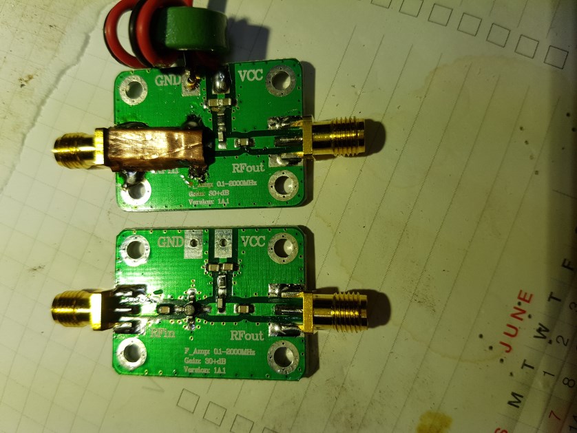
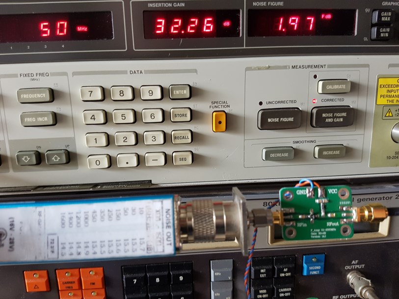
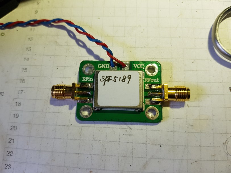
This is the screening using copper foil over the rf input see top preamp
to keep external RF out otherwise it interferes with the NF meter operation
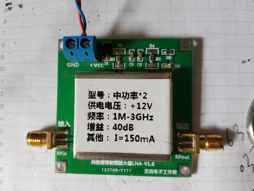
No. 1
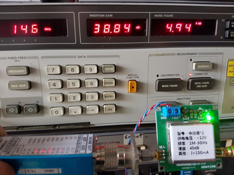
40 dB gain and 0.001
to 3.0 GHz
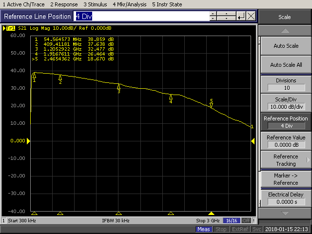
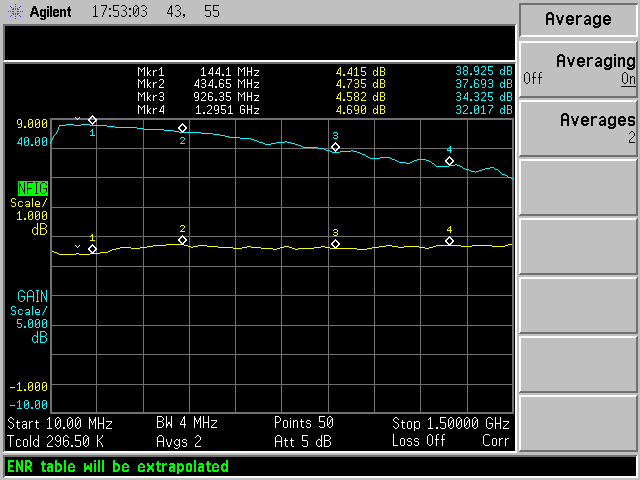
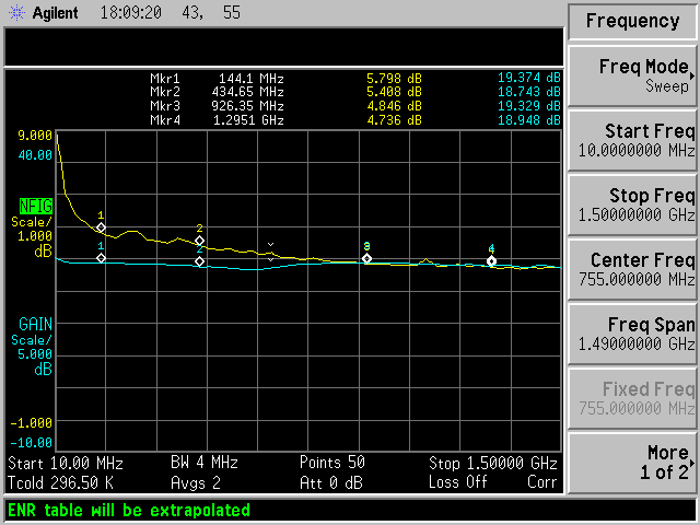
gain verses frequency response 300 KHz to 3 .0 GHz along with noise figures
10 MHz 36.04 db gain NF of 4.47 @ 12.27 volts
10 MHz 32.45 NF 4.12 dB @ 8.0v
50 Mhz 35.64 dB @ NF 4.09 dB 8.23 v
50 Mhz 39.03 dB @ NF 4.59 dB 12.00 v
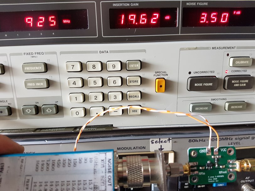
925 MHz 34.52 dB gain NF 4.97 @ 12.77 v
925 Mhz 31.09 dB and NF 1.44 @ 7.92.0 v
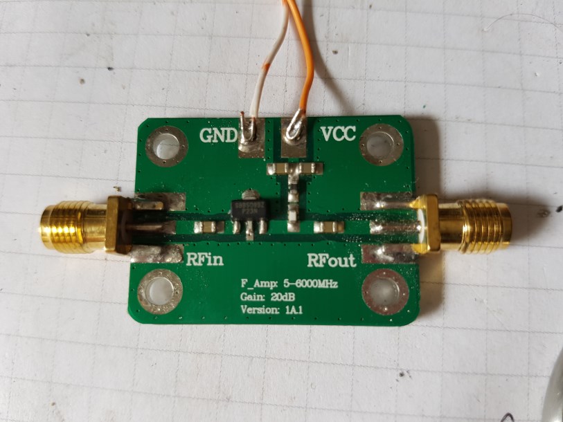
No. 2 5-6000 Mhz preamp
This amp is based on the RFMD active device SBB5089Z . It is .internally matched to 50 ohms, 5v operation and typically 75 mA. Gain is quite flat with a gentle downward slope to 6 GHz from 20.5dB to 15.5 at 6 GHz noise figure is 3.9-4.9 dB at 1950 MHz max output is 19.5 dBm at 50MHz-2GHz
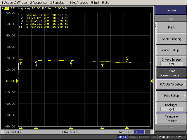
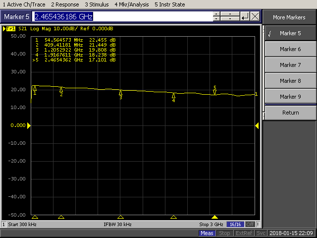
swept response 300Khz to 3 GHz ripple probably caused by coax leads !??
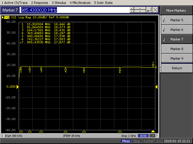
Response from 300 Khz to ~100MHz gain only dropped 0.5 dB !!
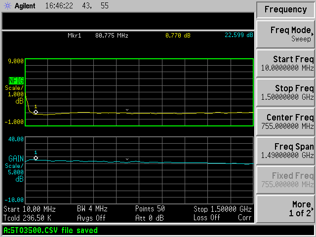
N8972A dual mode display
The measured gain of the amp on the VNA and the NF meter are different this could be due to the calibration of the noise source i used , to tight to purchase a brand new calibrated Agilent one
No.3 Avago mimic INA02184 identified by NO2 on top of mmic .. Data sheet .. 50 ohm in and out with a typical power gain of 31 dB…0 to 500 MHz noise figure of 2.0 db achieved at 35 mA (absolute max 50 mA) 3.5 dB at 2 GHz ,This module is configured for 12 V operation The 3db bandwidth is 0.8 GHz but it is essentially flat from 300Khz to 500 MHz and over ,max rf out is +10 dBm
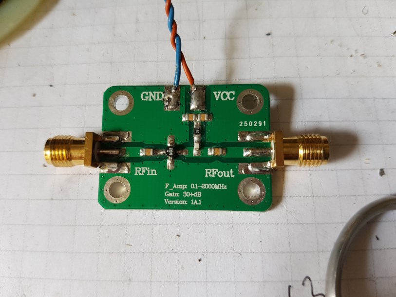
12v DC (or more correctly 38 mA) is best noise figure
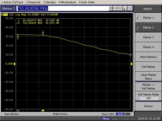
Particularly Flat frequency response 32+/- 0.5 dB to well over 500 MHz
.
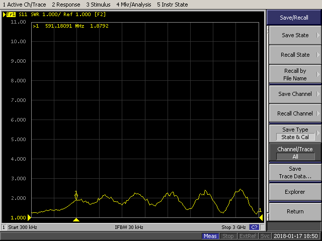
Avago input VSWR on the VNA
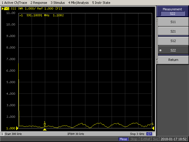
Avago output VSWR
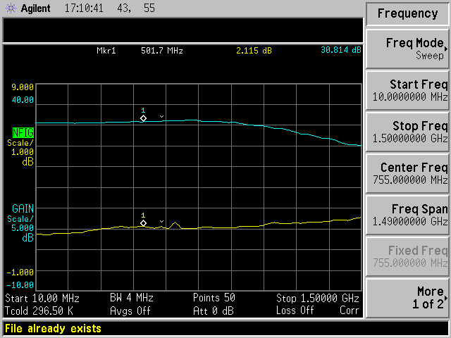
gain/ NF on N8972A note bump in noise figure.. that’s due to external RF pickup !!
hence the need for good rf free environment
N0. 4 5 - 3500 MHz
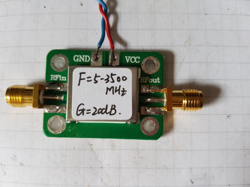
Unknown active device I will have to crack it open !!
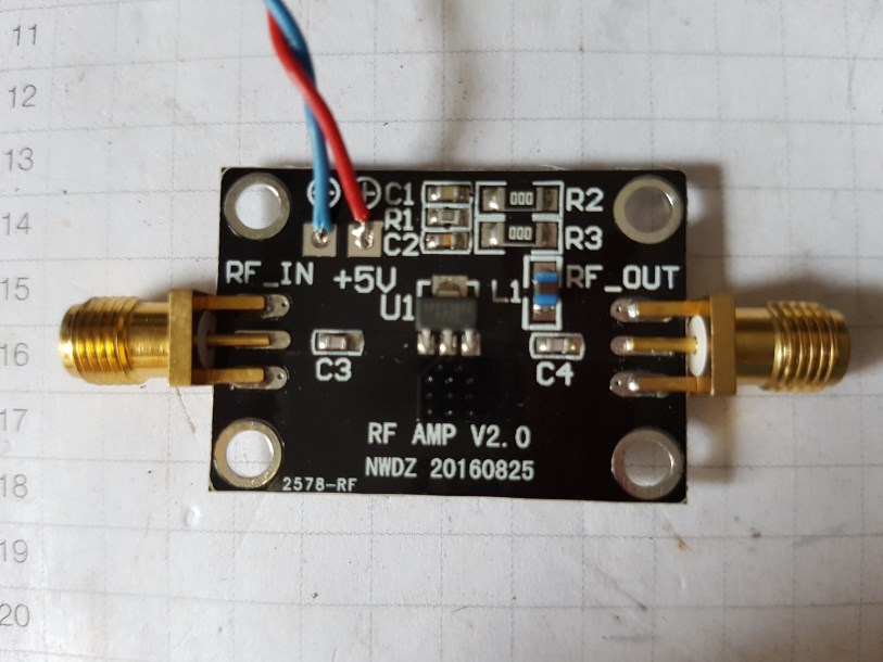
No.5 NDWZ preamp
Active device is a SPF5189Z 90 mA @5 v 26 db gain at 54 Mhz nominal 50 ohm input and output impedance .
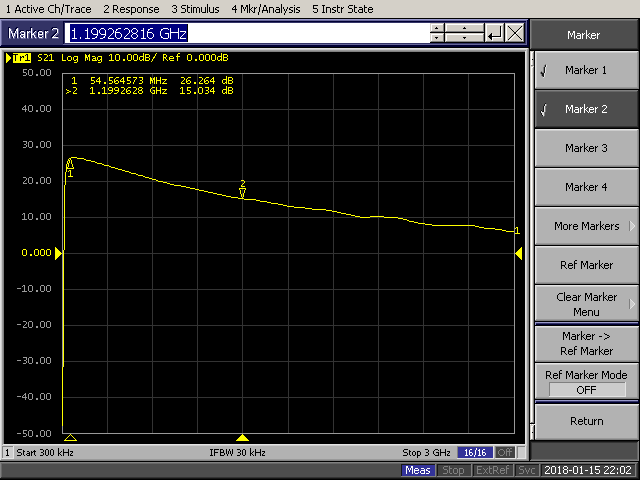
10 MHz 9.73 db gain NF of 3.86 @ 5.04 volts
30 MHz 24.53 dB NF of 1.35 @ 5.0 v
30 Mhz 23.89 dB NF 1.09 @ 2.98v
50 MHz 25.12dB NF 0.92 dB @ 2.26 v
50 MHz 26.35 dB NF 1.03 dB @ 5.0 v
150 MHz 26.19 dB gain NF 0.56 @ 5.0 v
150 MHz 24.9 dB NF 0.47 @2.26 V
430 Mhz 22.26 dB and NF 1.08 @ 3.34.0 v
430 MHz 22.65 NF 1.12@ 5.00 V
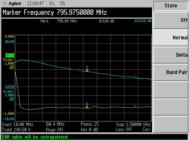
LNA Ultra-Low Noise Figure=0.60dB @900 mhz 18 db gain, 5v
and 90 mA
10 MHz 24.48 db gain NF of 5.06 @ 5.04 volts
30 MHz 26.16 dB NF of 1.63 @ 5.0 v
30 Mhz 24.55 dB NF 1.07 @ 1.98v
50 MHz 25.15dB NF 0.95 dB @ 2.76 v
50 MHz 25.92 dB NF 1.14 dB @ 5.0 v
140 MHz 25.31 dB gain NF 0.59 @ 5.0 v
140 MHz 24.22 dB NF 0.51 @2.36 V
430 Mhz 21.19 dB and NF .92 @ 2.39.0 v
430 MHz 21.99 NF .92 @ 5.00 V
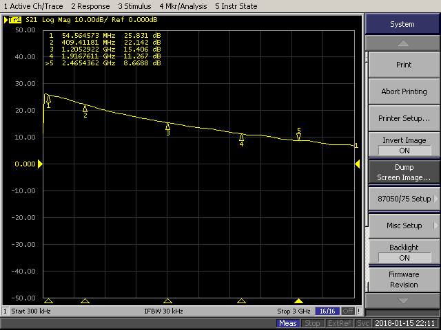
.SPF5189 device gain and noise figure
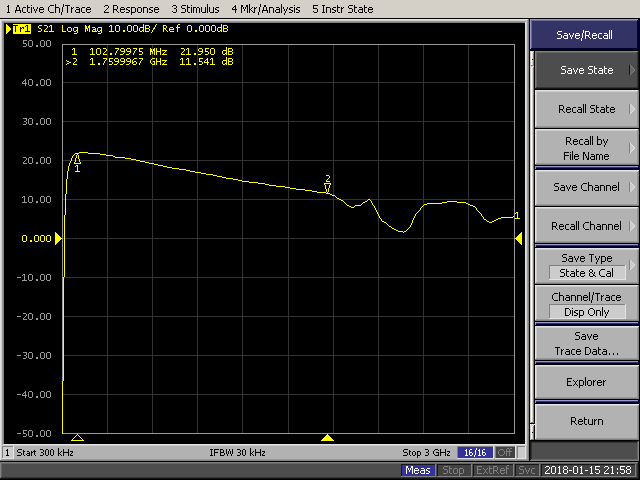
…No.7 TB 386 operates on 3-5 v
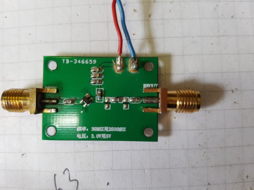
Unknown
Active device
10 MHz no good at 10 Mhz
30 MHz 13.95 dB NF of 3.35 @ 5.0 v
30 Mhz
10.4 dB NF 2.46 @ 1.97v
50 MHz 19.15dB NF 1.95 dB @ 5.00 v
50 MHz 17.00 dB NF 1.81 dB @ 1.98 v
146 MHz 22.26 dB gain NF 1.09 @ 5.0 v
146 MHz 20.90 dB NF 0.51 @2.53 V
430 Mhz
20.01 dB and NF 2.08 @ 3.2.0 v
430 MHz 20.56 NF 1.98 @ 5.00 V
There are some more I have to document soon as I
have data I will add it to here
73's Mike ZL1BTB