Super- regenerative Receiver at High Frequency (~2--3 MHz) M.A.Pinfold ZL1BTB
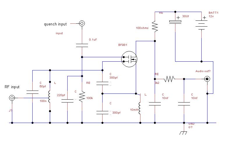
There are lots of recipes for super regenerative detectors at Low VHF through UHF and even SHF but I can find none at HF so I thought I would give it a try. I settled on a simple Dual gate mosfet Colpitts oscillator . I used a dual gate device as it is easy to control the oscillator with outboard quenching by application to gate 2 the circuit I used is seen below and there is nothing special about it. In fact the super regenerative principle can be applied to any oscillator ( in theory anyway ) and I have had a self quenched 10 GHz gun oscillator "quiet" on receipt of a 10GHz signal . For this investigation I used my Escort Function Generator to generate the variety of Quench frequencies and waveforms to try. The signal source is from an HP8640B generator in AM mode at 2.23 MHz !! I also connected the E4403B spectrum analyser up as well so I could look at the RF waveform generated in super regenerative mode. while I fed a signal from the signal generator.
The basic experimental receiver will hear a 1 uV 90%(-110dBm ) modulated AM signal as plain as day , you could hold a AM-CW conversation using this receiver without a problem, so the receiver has a noise floor way below the background terrestrial noise level received off a dipole at HF ( but when you see the analyser display you will see why you would NOT really want to connect this receiver to a dipole without a low gain RF amp with very good reverse isolation ahead of it ) I got the receiver going ok and then discovered that the quench waveform and frequency does have operational limits . There was a maximum frequency and quench voltage range beyond which the receiver performance started to degrade . It was also seen that with this receiver quench waveform was important Square wave quench mode was hopeless , the receiver performance was dismal, huge input signals were required to achieve good performance. . To try and obtained some uniformity to the experiment, I connected a Sinadder (S/N meter) across the loudspeaker terminals of the amplifier that I used to hear the demodulated audio output of the receiver . I chose the 12dB as my reference point to base my measurements on. All my frequency and amplitude measurements were adjusted to achieve a "12 dB s/n ratio" .
I adjusted the quench frequency in 5 Khz increments from 20KHz up to 80 KHz and noted the amplitude level to achieve a 12 db S/N the graph shows the performance achieved.
Graph of quench frequency verses quench level for 12 dB S/N
Here is the free running osc at 2.35 MHz but it is relatively clean, note the second harmonic approx 25 dB down
Here is the screen shot of the super regen in operation, see why we don't really want to connect it directly to an HF dipole at the frequency of operation
This is the super regen in receive mode . look at the broadband noise pedestal formed around the carrier , caused by the quench frequency sine wave at 20 Khz and 0.26 volts pk-pk into gate 2 of the mosfet . not a pretty sight see also the peak level has fallen to -24. dBm however I suspect the combined RF energy under the curve will still equate to the original -2.0 dBm of the original free running carrier, unfortunately my analyser does not have the extra memory installed to enable the software to measure the rf power of this waveform. The RF spectra of square wave quenching was even worse !!
I did actually circum to curiosity and connected it up to my 5 Mhz HF dipole to hear what it could pick up , I changed the tuned circuit to tune 80m , .The tuning was very broad , I could hear AM sw stations at 3.9 Mhz clearly, and ssb stations sounding like the typical am demodulation . Now here's a quest ! all the information to demodulated the ssb is there , so how do we demodulate it analogue techniques ?? up mix with a audio osc then down mix again?? what I did notice is that the Super regen rebroadcasts what it hears ,I could here and demodulate LSB SSB on 80m if I placed the AOR3000A scanner with its whip antenna ,near the super regen .You can tune around and demodulate separate signals . The circuit appears to amplify in a broadband way , although you can peak up the received signal in the super regen. What I did notice that tweaking the quench variables will affect the audible demodulation from the super regenerative receiver however it had a much lesser effect on the quality of the rebroadcast signal as heard on the AOR3000 receiver ., I switched the Signal generator to FM and turned the level up to -80 dBm, I found that I had to go to about 20 Khz deviation to hear anything , It definately demodulates by slope detection as I could tune either side of the centre frequency and hear the 1000 Hz modulation tone increase and then fall away as we moved up and down the passband slope . I was somewhat dismayed at the lack of sensitivity to slope detection of FM. I thought that because the Q of the tuned circuit would be high at 2,24 Mhz, that the recovered audio would be good at low deviation ! but it wasn't, another question to answer ??!!
All in all an interesting exercise into some of the workings of the super regen! I have not worked out why the performance of the receiver should fall off as the quench frequencies increase?? some receivers quench at 100khz and still have good sensitivity , when I look at the waveform on the Fluke scopemeter, there appears plenty of time for the oscillator operational pulse to decay for quite some time before the quench pulse triggers the oscillator again .