Second generation reciprocating
detector (from Ham Radio Oct 1978)
By
Stirling Olberg, W1SNN, 1~ Waltham, Massachusetts 02154 ( silent key )
The
"reciprocating detector' was designed by R.S. Badessa at M.I.T. The RD
features a carrier-synthesized reference signal and requires no external bfo.
The circuit offers advantages over conventional detectors in that it adjusts its
bfo level automatically in proportion to the average signal level received.
First introduced in ham Radio in March, 1972, the RD has gone through several
metamorphoses. The version presented here uses ICs and can be used in modern
receivers using semiconductors. Also included is a design for a 10.7-MHZ ssb
filter for single-passband receivers. Editor.
An
updated version of the reciprocating detector,which can be used in solid-state
receivers with high-frequency i-f strips
During
the past three years I've had many requests for revisions to the reciprocating
detector circuit so that it can be used directly at high frequencies. Here's an
updated IC design that can be used at frequencies up to 20 MHz.
Background
Early
attempts to directly use the RD above 5 MHz
required
very careful circuit layout to reduce or eliminate inter-circuit coupling, and
in particular to maintain the correct phase relationship required in the
feedback loop. Also, the detector portion operated as a half-wave rectifier. A
current-regulating source had to be adjusted to cause the signal diode to
operate at a level just below conduction, so that at frequencies above 5 MHz the
diode and its circuitry ceased to perform uniformly. Result - a badly distorted
detected signal.
Despite
the distortion, in some cases the circuit performed well enough for signal
identification. But much was to be desired. A cure for individual cases was to
adjust the bias level for the current-source diode until it just conducted on
noise. In most cases, with a tube receiver that produced i-f signals to the RD
input exceeding the saturation level of the complete circuit, a clipped response
occurred. Single sideband signals then became unmanageable because of widely
varying signal levels that couldn't be controlled by the agc systems in older
tube receivers.
The
original circuit was designed to be used in receivers such as the Collins 5151
and Drake R4A, which have highly selective dual or adjustable filters in the
receiver i-f passband. In the 5151 receiver the i-f output was fed to the RD
through a cathode follower; the maximum output level could not exceed 3 volts.
The application using the Drake R4A employed enough attenuation through the
coupling to the original product detector output transformer to preclude
saturation.
An
updated design, which uses ICs, allows the RD to be incorporated into more
modern receivers. Models of the new circuit have been made for 10.7, 16, and 20
MHz. Test models were constructed using point-to-point wiring. Later models used
PC boards.
Circuit
description:
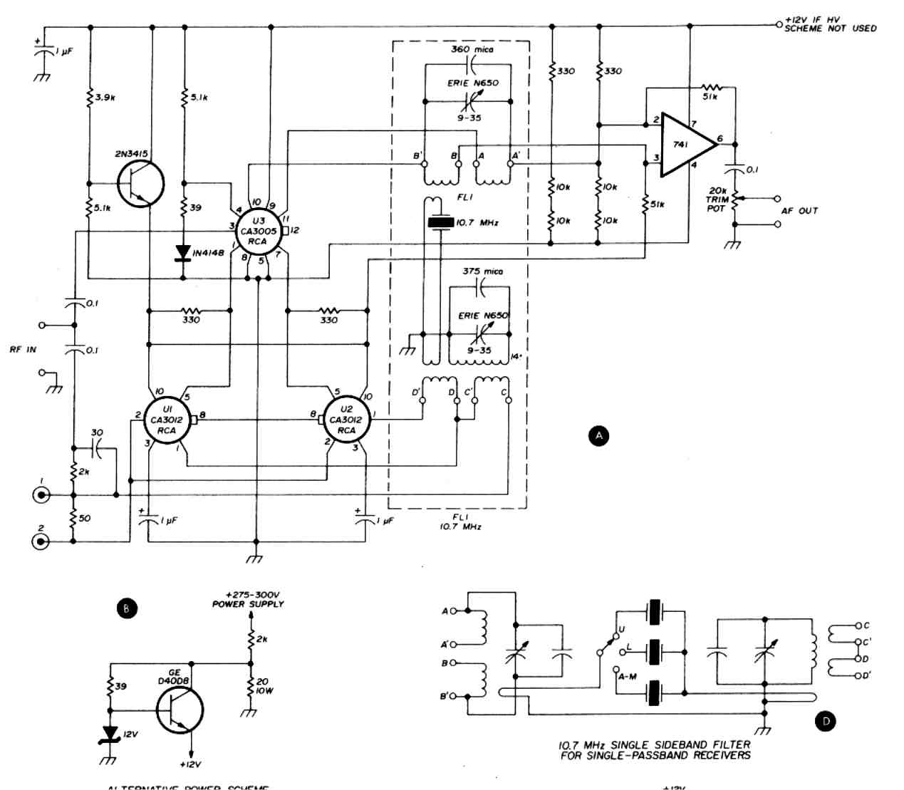
The
circuit consists of two amplifier chips, ICl, and IC2 (fig. 1). These are
monolithic wideband amplifiers with frequency response between 10 kHz and 20
MHz. These chips are 10-lead devices in TO-5 cans. A third rf amplifier, IC3 is
a balanced differential amplifier using an internal constant-current source,
which eliminates the orignal problem caused by the biased half-wave rectifier.
This amplifier operates from 0-100 MHz. This wideband response allows the
circuit to work in the same manner as the original current source for the
detector and as the reciprocating switch. These two functions are improvements
over the old circuit. The dynamic range improvement alone is worth the effort.
Tracing
the signal through the circuit, we see that a capacitive input circuit couples
the rf signal into IC3 input. The capacitive coupling isolates any direct
current that might be superimposed on the rf signal from the i-f ouput circuit.
The input signal is then applied to a phase-shift network, then to one set of
inputs of IC1 and IC2. These three inputs are then provided with a signal path
that's essentially in series with the reference signal, or beat frequency
similar to a conventional product detector.
fig.
1. Schematic of the reciprocating detector MKII using wideband-amplifier ICs,
(Al. Also shown are an alternative power scheme fior receivers using a
high-voltage dc supply,
a
test setup for adjusting the filter, (CI, and a schematic for a 10.7-MHz ssb
filter,
The
reference frequency is generated by filtering a portion of the received signal
through a narrowband crystal filter, FL1. The push-pull output of this filter.
feeds this signal into the balanced inputs of IC2 and IC3. We now have the
circuit reference by virtue of a carrier-controlled feedback loop. The feedback
loop response time is determined by the slow recovery time of the narrowband
filter; therefore, noise pulses are reduced or eliminated.
IC4,
an op amp, is an audio amplifier. The received-signal audio envelope is taken
from the input filter, FLl, then applied through two lowpass filters to the 741
IC. This amplifier audio gain is established by the feedback resistor (51 k).
This value may be changed for a higher or lower level; however the gain will
overdrive the first audio inputs of most communications receivers. A 20k trimpot
at the audio amplifier output allows gain control.
The
RD will work in any receiver if its i-f matches that of the RD reference filter.
For best results, narrowband i-f filters offering high selectivity are a major
requirement. Many receivers use dual filters offset by the correct dispersion to
allow either sideband to be selected by switching in the appropriate filter
section. Others use adjustable filters to obtain the same effect. I-f passband
circuits using single filters, as in many of the older tube receivers, also
perform nicely. With 1.8-kHz filters, however, only one side can be used unless
the reference or beat frequency is displaced to center the signal in the filter.
The older reciprocating detector circuits didn't provide for this problem.
Circuitry
to show how a filter can be constructed for upper/lower sideband selection for
use in receivers with single passband filters, incorporating three crystals, is
shown in the filter circuit. If your receiver uses filters to select sidebands,
then only one crystal, set in the i-f passband center, will be
required
.
Construction
of a 10.7-MHz RD filter
The
filter used in an RD is not a complicated device. It has a shape factor similar
to that of the old variable crystal filters. It's not a wide passband filter
because it's used to select the beat-frequency signal.
On
a Micro Metals T50-2 toroid core wind 14 turns of 0.2 mm Ino. 32) enameled wire.
Secure the wire so it won't become loose. Use tape or nylon string. Make sure
the coil leads are at least 30 mm (1-1/2 inches) long and are scraped clean of
insulation. Next, fold a 30-cm (12-inch) length of the same type wire in half.
Twist this pair of wires until you have at least eight twists per 25 mm, or 8
twists per inch. (This is called a bifilar pair.)
Now,
using the bifilar pair, wind on the same form a three-turn winding and secure
it. This coil should be wound in the area not used by the previous winding, but
it isn't important that it be exactly placed or spaced in this area. Next clean
off each of the wire ends; then, with an ohmmeter, identify each coil
separately. They will be used to complete the connections identified in the
filter drawings as C, C', D, and D'.
After
each winding has been identified, the ends opposite each other can be connected
to provide the center-tapped winding signified as C' and D in fig. 1. This
toroid will contain three coils. Now, on a second core of the same type, wind
two eight-turn windings of the bifilar pair and scrape the four ends. Again,
with an ohmmeter, identify each coil. These ends can be designated A, A', B, and
B'.
Mount
each coil on the PC board as shown (fig. 21. If you're not using the board,
mount the coils about 30 mm (1-1/2 inches ) apart. Don't tighten the coils yet.
Next, mount the crystal between each toroid, then wind a single turn of 0.2 mm
Ino. 32) enameled wire on each toroid, terminating one end of each coil on a
crystal terminal or the switch, whichever the case may be. The other two coil
ends should be connected together.
If
your receiver has selectable sideband filters, a single crystal will be
required. If not, then wire it as shown in the filter diagram Ifig. 1) and
include all three crystals. In this case, a selector switch must be used at the
filter location. If this is the case, connect the link ends from the two coils
to the appropriate switch contacts. Reed switches can be used and provide
excellent low-loss control.
The filter components are for 10.7 MHz but will work at 9 MHz with different crystals.
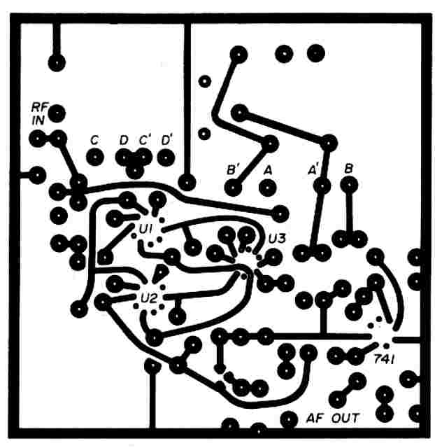
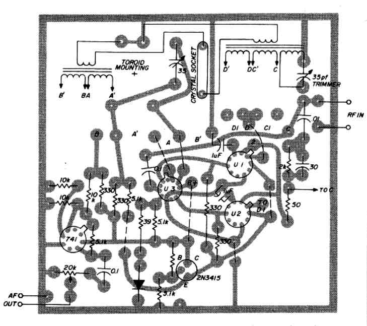
fig. 2. PC-board layout for the updated reciprocating detector ,fig. 3. Component placements for the reciprocating detector circuit board.
The
components can be juggled to work around that frequency range. Lower frequencies
will, of course, have a higher inductance value.
The
crystals can be purchased from any of the manufacturers currently advertising in
most of the amateur magazines. It's best to use fundamental-frequency crystals
mounted in an HC6/U holder, with wire leads to make soldering easy. This doesn't
preclude other types of holders or pin-mounted crystals; however, some of the
alignment procedures will be a little more difficult, particularly if
pressure-type holders are used.
Checkout and test
Connect
a signal generator and scope or rf voltmeter through terminating resistor R as
shown in the test setup. Set the indicator to a high sensitivity and the signal
generator to a high output level. Carefully tune the signal generator across
10.7 MHz. An indication with a very sharp upswing in level will occur when
passing through crystal resonance. Carefully adjust the signal generator to the
peak of the upswing. Then, with an insulated screwdriver, adjust the 9-35 pF
capacitors for future increase. The scope sensitivity and the signal-generator
output level will have to be reduced as the resonance of each coil is reached.
Frequent readjustment of the signal generator will be required to keep it
centered at crystal resonance. As the adjustments proceed, you'll notice that
the sharp increase at the crystal frequency will become easier to adjust.
If
a three-crystal unit is to be constructed, make these adjustments at the
passband center or with the a-m crystal in the circuit. The other two crystal
frequencies are as sharp as that of the a-m resonant frequency and will be
within the inductor resonant frequency.
To
use the RD in the ssb mode with a single i-f passband filter, it won't be
necessary to offset tune the receiver. Simply use it as you normally would. It's
like having a crystal controlled bfo - simply switch in the appropriate crystal.
RD construction:
The
reciprocating detector is simplicity itself to construct. Attention to component
placement is similar to that of any high-frequency device. The filter leads can
be connected, after filter adjustment, to those points shown Ifig. 11 that are
alphabetically marked. Use leads as short as possible.
A
slight tweaking of the filter might be required after it's installed in the
receiver. Use care as to the length of the lead to the RD rf input. This is a
twoway street: if the lead is too long, external pickup can cause interference
to the hf i-f stages; if the lead is shielded and too long, it can detune the
i.f stage to which it is connected. So a short signal path is required, or an
emitter or source follower will be required to reduce these effects.
The
choice of how the audio is routed is up to you. It can be connected as shown in
the references or used with an external amplifier. Since the output level is in
the 100-millivolt level, it can easily drive an external amplifier.
power supply:
Power
requirements for the new RD are further simplified. The older unit required a
dual balanced supply source, but this unit requires a single 12-volt supply at
40 milliamperes. The RD supply can be taken from the receiver supply filter
output if it's 12 volts. Or you can use a higher-voltage supply, such as found
in a tube reciver, if you use the alternative supply scheme shown in fig. 1.
Reference:
1.
Stirling Olberg, v iN, "Reciprocating Detector ham radio march
1972, pages 32-35.
bibliography
Olberg,
Stirling, WlSNN, "5-MHz WWV Receiver," ham radio, November, 1972,
pages 44-49.
Olberg,
Stirling, W1 SNN, "Reciprocating Detectof Converter," ham radio,
September, 1974, pages 58-63.