Reciprocating
detector For SSB /DSB/ CW
By
The Late Stirling Olberg W1SNN in
Ham Radio Magazine
March 1972
This
novel circuit has many advantages over conventional detectors since it
automatically adjusts its bfo level in proportion to average signal level.
A
paper presented at the International Communcations Conferencel during June 1971
described a synchronous detector which should be of interest to amateur radio
operators. The circuit was designed by R. S. Badessa while working on a project
at Massachusetts Institute of Technology. Mr. Badessa made further
investigations through support given by Damon Corporation where we both are
employed.
The
circuit was primarily designed for double-sideband, suppressed-carrier (dssc)
detection. It has been used in several communication receivers as a second
detector
and exhibits features which make a superb demodulator for CW, a-m, dsb and ssb.
The
name, "reciprocating detector," seemed appropriate to the inventor who
described the detector's operation thus: "Because a suppressed carrier wave
assumes either of two diametrically opposite phases in sequence, the detector
channels these into a smoothly rotating reference vector."
The
design features a carrier-synthesized reference signal and therefore does not
require an external beat-frequency oscillator. Because of other characteristics
of the circuit, impulse noises are rejected. Also, the average reference level
is proportional to the average signal level. The CW DX chaser and moonbounce
enthusiast can appreciate the desirability of this important feature of the
detector when he remembers what bfo hiss noise does to a weak signal as it goes
into a fade.
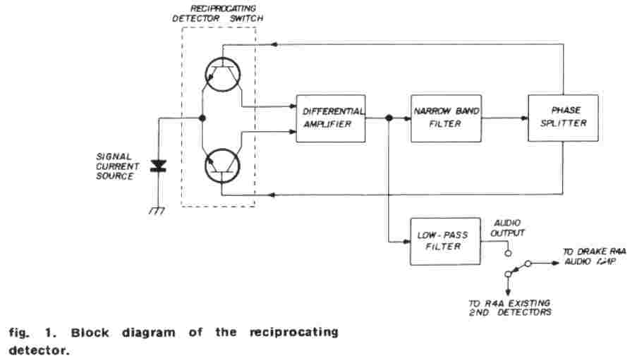
circuit
operation
a
signal flow diagram. An rf signal from the receiver i-f system is presented to a
half-wave diode detector. The detector provides a signal current source which is
fed to an electronic bidirectional switch. The two outputs of this switch are
directed into the inputs of a differential amplifier. The amplified output is
fed into a narrowband i-f filter and a low-pass filter. The narrow-band filter,
approximately 500-Hz wide, is coupled to a phase splitter which returns the
outputs to the inputs of the bidirectional switch; this filtered signal is the
reference. The low-pass filter allows the audio component to pass into the
receiver audio system.
Previous
experiments allowed the investigator to choose, by means of a selector switch,
existing detectors in a Collins 51S1 receiver or the reciprocating detector.
Later, simultaneous records were maide from each detector for comparison.
The
circuit diagram, fig. 2, is for incorporation into a Drake R4A receiver.
It is possible to use the same circuit in any other communication receiver with
appropriate modifications to the filter FL1.
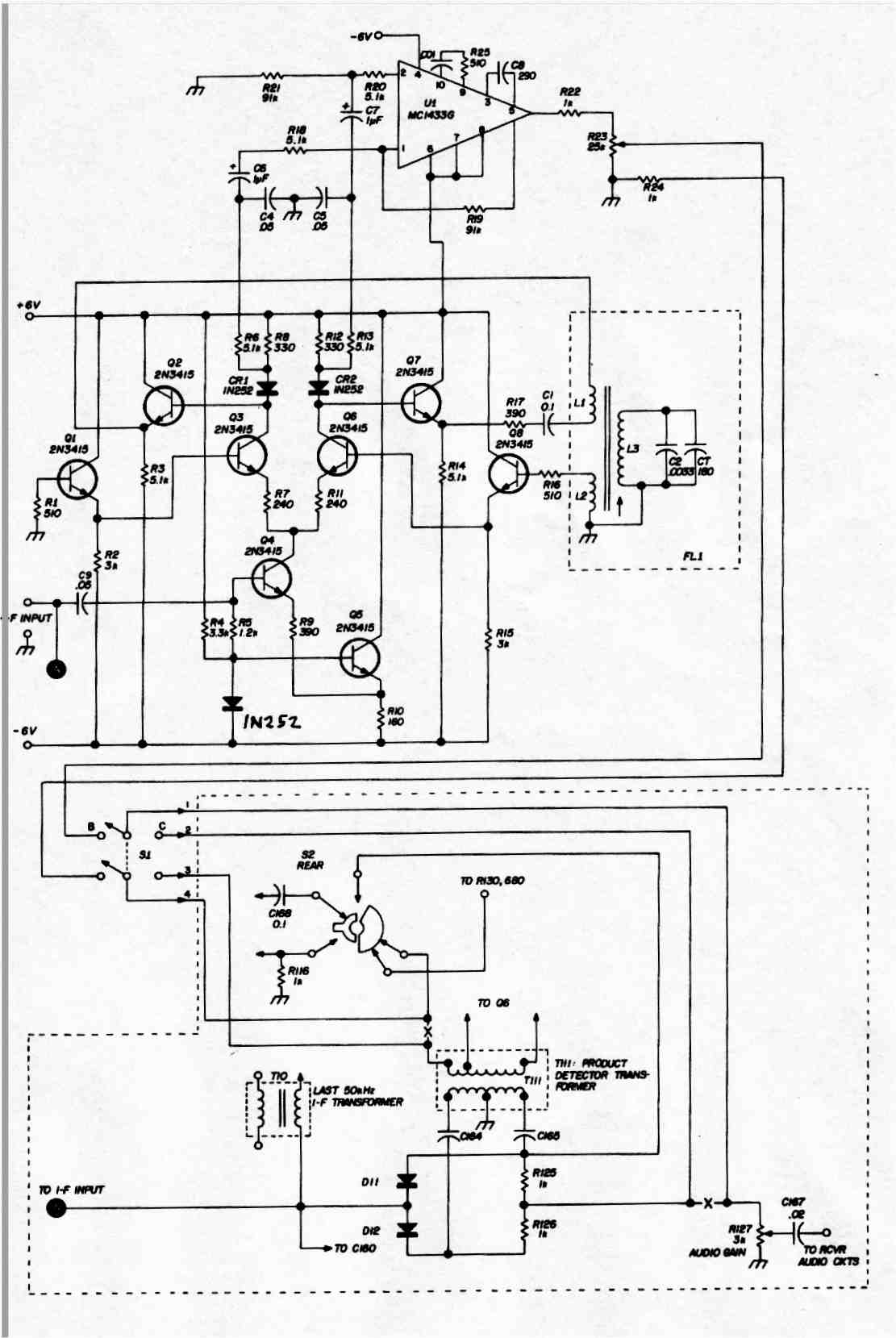
fig. 2. Reciprocating detector circuit, showing its installation in a Drake R4A communications receiver. Windings of filter FL1 are wound on Ferroxcube pot core and bobbin type 1811GA250-387; L1 is 5 turns no. 32 enameled, L2 is 43 turns no. 32 enameled, L3 is 109 turns no. 31 enameled. CT turns L3 to 50 kHz.
The
modification to the Drake R4A involves rewiring the CW/SSB/AM selector switch.
All changes are temporary; this allows the receiver to be restored to its
original state. At W1SNN the detector was permanently installed in the R4A. The
crystal switch, designated S4A/B in the Drake Manual, located on the left side
of the R4A receiver, was disconnected from the vfo/crystal circuitry. The vfo
was permanently connected, freeing the switch used for S1. A dpdt toggle switch
can be externally mounted in a convenient location on the operating table if you
don't want to use S4A/B for this modification.
The schematic diagram shows the rewiring of the CW/SSB/SW switch. It should be wired exactly as shown.
Other
wise, problems with the receiver bfo will result. The bfo must be off when the
reciprocating detector is switched in or a steady beat will be heard due to bfo
leakage into the receiver i-f circuits. This switch is designated S2 rear in the
schematic diagram and in the Drake instruction manual.
The
power supply circuit shown in fig. 3 provides the required voltages. The
voltages are higher than called for in the diagram. It is important that the
voltages be very nearly the same level; in excess of six volts is permissible,
provided that the two are equal. They should not exceed 10 volts, however.
Resistor
R24 must be included to complete the voltage drop through the voltage divider
when the bfo is removed. Therefore, when the reciprocating detector is switched
in the connections to S1 must be made as shown.
The
direction in which the windings for FL1 must be wound is important. If they are
in the wrong "sense" the filter will not operate.
TUNE
UP
FL1
has a small adjusting slug which tunes the filter to the center frequency, 50
kHz. Put the CW/SSB/AM switch on ssb and S1 on the receiver's own detector; tune
in an ssb station, and switch S1 to the reciprocating detector position. If the
voice sounds higher or lower in pitch than normal, adjust until the voice pitch
sounds correct, by switching back and forth between the two detectors.
Adjustment is complete when no difference in voice pitch is noticed. R23, an
audio gain trim potentiometer, can be adjusted at the same time, rocking the
switch in the same manner; this pot will set the audio output level of the
reciprocating detector the same as the receiver detector output level.
Operation:
When
the detector installation adjustment is complete, you can compare signals by
simply flipping switches. At first very little difference will be noted in the
comparison between detectors.
On
160 meters, with the receiver a-m detector switched in and the noise blanker
off, an a-m signal was tuned in. Some interference from a Loran station was
present. Switching to the reciprocating detector a beat signal was heard;
re-tuning the signal very slightly produced a zero beat which has a very narrow
lock-in range. No difference in audio quality could be noticed, and the Loran
signal was greatly subdued.
Switching
in the noise blanker eliminated the Loran signal pulses completely; switching
back to the receiver a-m detector with the noise blanker on, the pulses were
subdued but very difficult to copy through. The reason the reciprocating
detector eliminated the Loran pulses is because the reference filter Q is too
high to allow the filter to "build up." Ignition pulses, static
crashes and flat-topped linears are treated in the same way.
Tune
in the Canadian Standard Time Signal or an overseas broadcast (plenty of them on
40 meters). The receiver detector should be on a-m. Notice when the signal fades
that sometimes the modulation will become distorted; this is selec tive fading.
Switch in the reciprocating detector and the distortion will disappear.
Next
try CW. Look for the very weak ones and notice that when fades occur on the
conventional detector, the signal disappears. Switch to the reciprocating
detector, it's still there! This is because the reciprocating detector produces
its own beat signal which is proportional to the received signal level. When the
conventional detector is on, its bfo level is constant, and so is the low level
hiss it produces, acting as a mask for the weak signal.
Sideband
operators will appreciate the reciprocating detector because adjacent channel
signals which chop up a QSO because they are near the i-f passband are now
subdued. Flat-topped linears and lightning noises are almost eliminated by the
reciprocating detector; the latter will be completely out of the picture if the
noise blanker is used as well.
summary
This
unique circuit is well worth the work that has gone into its installation. It is
hoped that other amateurs will try it and perhaps find some features we missed;
or try to shoot down those reported. To Steve Badessa goes my thanks for the
circuitry and his help in incorporating it in my receiver. To my wife, WA1 IKR,
who typed and typed and typed, many thanks.
reference
1. R. S. Badessa, "A Communications Detector with Signal-Synthesized
Reference," IEEE International Conference on Communications, Montreal,
Canada, June, 1971.
ham
radio
Amplitude modulation detector for single sideband or suppressed
carrier input
USA Patent US3430151A
Inventor Rosario S Badessa