Plessey Avionics PTR3411 " Groundsat"
I' m told (on extremely good authority) that approximately 100 of these were sold and in 1980 they were selling for about 5000 pounds sterling ! They have not been manufactured for about 20+ years , unfortunately the Plessey Avionics company no longer exists in its original form and has been gobbled up a long time ago and the remanents may be under the large German electronics Siemens group.??? If you have or know the where abouts of any of these "groundsat" units please let me know I have a fascination for them!
Below
is a collection of information that was kindly sent to me By Chris Richardson ,
also a UK radio Amateur , G3NAE
whose "baby" it actually is, his name appears on the
American patent No. 4134068 ( and on various other comms patents) for this radio communications technique ,
He is still doing advanced research work on this concept , ( and
others!)
Visit
our website at www.roke.co.uk
Roke Manor Research Ltd, Roke Manor, Romsey, Hampshire SO51 0ZN, UK.
The concept is hard to swallow when you first read of it however think of it this way , There are a lot of 10 Ghz /24 Ghz WBFM transceivers about that are able to run Full Duplex communication ,( talk and listen AT THE SAME TIME) They usually use an Intermediate Frequency of 30 Mhz , For duplex comms to work, you must transmit with an offset of 30 Mhz between both stations at 10 Ghz./24 GHz ( so far so good ! ??) ok so we change our IF to 10.7 Mhz , full duplex concept still works and the concept is perfectly understandable ?? ok lets change our IF to 100 Khz concept still understandable ?? 10 Ghz/24 Ghz oscillators are now 100 Khz apart to get the 100 Khz IF .. OK now l suggest we change our IF to dc or "ZERO IF " ( baseband , ie audio frequency 300-3KHz, IF as in a direct conversion SSB receiver) they work ok dont they ?? Now you can see how we can still achieve full duplex communications ( transmitting and receiving ,CONTEMPORANEOUSLY !) on the same frequency! There are some constraints to this and they are to do with the intercept point of the receiver mixer, L.O phase noise etc and methods to minimise the deleterious effects of these on the quality of the received signal at microvolt level , .after my "simplistic" explanation , are you now convinced that this is possible!.
Groundsat
is a compact VHF (FM) Manpack Transceiver offering unique facilities.
Designed primarily to improve the
^Single
Frequency Tactical Manpack Repeater/Rebroadcast Station
Ģ^Operates
on the same frequency as your radio network
Ģ^Dramatically
increases the chances of 'getting through*
Ģ^Unattended
operation
ĢEases
frequency allocations
Ģ^Full
military specification and frequency range (30-76MHz)
LIST
OF CONTENTS
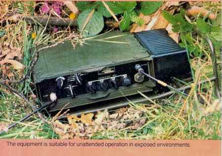
Groundsat deployed for action !

General
Common
channel rebroadcast
Duplex
operation
Simplex
operation
Additional
facilities
ADVANTAGES
OVER CONVENTIONAL SYSTEMS
Frequency
planning
Operator
convenience
Performance
Deployment
Communications
limited by difficult terrain Enhanced performance achieved by Groundsat
PRODUCT DESCRIPTION
2.1
GENERAL
The
Plessey Groundsat* System is based on the PTR 3411 VHF Transceiver,
This is a compact, manpack v.h.f. (f.m.) transceiver covering the
military frequency range from 30 to 76MHz in 25kHz channel increments.
The system embodies a revolutionary new concept in communications
technology, permitting simultaneous transmission and reception on a common radio
channel. As a result, the *Groundsat1 system is perhaps the most versatile ever
offered in the military tactical radio communication field. The following modes of operation are available;
|
(a)
Common channel rebroadcast
(b)
Common channel duplex
(c)
Simplex |
These
are described in the following sections.
2.2
COMMON CHANNEL REBROADCAST
By
virtue of its unique ability to receive and transmit simultaneously on the same
radio channel, the system is capable of rebroadcasting received narrow-band
frequency-modulated signals without channel translation, giving a signal power
enhancement in excess of lOOdB (lO117 times), In this mode, the system is
designed for unattended opŁeration, remaining in its 'Standby* condition until
required for use by a subscriber. The
subscriber transmits a command signal which activates the rebroadcast
transmitter.
The rebroadcast station then transmits an acknowledgement tone to the
initiating subscriber to indicate that it is operational and ready for use. The station remains operative for a nominal period of 45
seconds. The end of this
rebroadcasting period is signalled by the transmission of a 'time-out* tone,
after which the reŁbroadcast station reverts to its 'Standby* condition. The
rebroadcasting period may be extended at anytime by transmission of a further
command signal - it is not necessary to wait until 'time-out* has occurred.
An
audio tone is heard in the receiver earpiece if both transmitter and receiver
are in an operational state. The test may be performed in radio silence if the
antennas are not connected. Alternatively,
it may be used in conŁjunction with the deployed antennas to provide the
operator
with a subjective means of selecting the optimum re-broadcast transmitter power
for use in a particular situation. if desired.
Additionally, a local operator may initiate
2.3
DUPLEX OPERATION
This
mode of operation permits two PTR 3411 'Groundsat' stations to interoperate to
provide a full duplex radio circuit for analogue speech signals, using the same
radio channel for transmission and reception.
In order to avoid operational problems which might arise from the
continuous radiation of a radio carrier even when the link is idle, the standard
equipment configuration provides 'press-to-talk* transmitter operation in this
mode,
2.4
SIMPLEX OPERATION
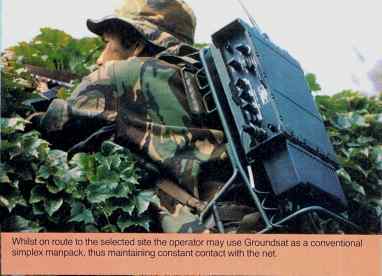
In
this mode, the PTR 3411 'Groundsat* equipment operates as a conventional,
narrow-band f.m. simplex manpack, with a maximum power output of nominally one
watt. A Clansman-compatible tone
squelch system (150 HZ )is used. The antenna
is a 1.5m broadband whip.
2.5
ADDITIONAL FACILITIES
Two
test facilities are available at the equipment front panel.
These are described below.
2.5.1
TEST OVERLOAD
This
test mode is provided to assist in the deployment of the antennas in the
'rebroadcast' or 'duplex* modes. These
t;wo modes of operation utilise separate transmitting and receiving antennas and
whilst their deployment is by no means critical, the 'test overload* facility is
provided to indicate to the operator the minimum antenna separation necessary
for optimum performance of the system. The test mode provides a continuous tone in the handset
earpiece if the antennas are sufficiently separated for optimum operŁation,
The tone ceases if the antennas are too close toŁgether.
2.5.2
TEST TRANSCEIVER
This test permits the operator to perform a rapid and comŁprehensive 'loop-round* check on the operational state of the transceiver. Operation of the handset pressel switch in this test condition modulates the transmitter with an audio tone and switches on a calibrated r.f. test signal.
3.1
ADVANTAGES OVER CONVENTIONAL SYSTEMS
The
'Groundsat' System offers significant advantages over conventional
rebroadcasting systems. These
stem from its unique capability of rebroadcasting without the need for channel
translation, from the wide range of
3.1
FREQUENCY PLANNING
Combat
net radio transceivers in current use employ single frequency simplex operation.
In view of the varied nature of
The
'Groundsat* system using the same radio channel for reŁception and
rebroadcasting, avoids all these problems.(Figure
3.2). It is capable of operation on
any 25kHz inŁcremental channel between 30 and 76MHz simply by selecting
3.2
OPERATOR CONVENIENCE
The
advantages offered by the 'Groundsat' system in this respect may be considered
in two categories.
The
second aspect of operator convenience is seen when considering the requirements
of subscribers to the rebroadŁcast
3,3
PERFORMANCE
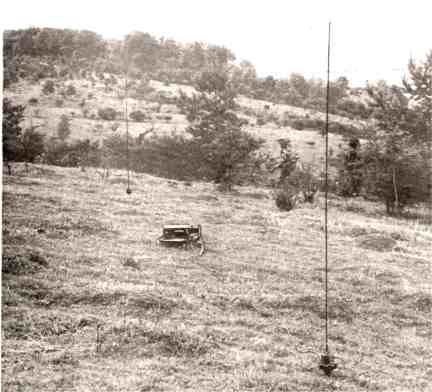
The
improvement which may be expected in net coverage when using the 'Groundsat*
system is illustrated in
3.3
With
a headquarters station located in a valley as shown.
3.4
DEPLOYMENT
Some
of the advantages concerning ease of deployment of the 'Groundsat' system have
already received mention 'in the
ENHANCED PERFORMANCE ACHIEVED BY GROUNDSAT
4.1
MECHANICAL
The
PTR 3411 'Groundsat1 transceiver (Figure 4.1) comprises a v.h.f. (f.m) manpack
transceiver, housed in a sealed and
(i)
Transmitter antenna connector -
50
ohm BNC
(ii)
Transmitter volume control switch
(iii) Transmitter power control switch
(iv) Operating mode switch with the
following
positions:
'OFF'
SIMPLEX
" DUPLEX REBROADCAST TEST TRANSCEIVER TEST OVERLOAD
(v)
Four frequency setting switches with the following functions:
(a)
10MHz steps
(b)
1MHz steps
(c)
0.1MHz steps
(d)
0.025MHz steps
(vi) Audio
connector - 7 pin Clansman
(vii) Receiver antenna connector -
Internally,
the case is divided horizontally by a central screening partition;
the lower section created by this partition
4.2
The
electrical circuits are contained on seven double-sided printed circuit boards,
each board having components mounted
4.2
ELECTRICAL
Electrically,
the equipment consists of the following assemblies:
(i)
Transmitter
(ii)
Synthesiser
(iii)
Voltage-controlled Oscillator
(iv)
Receiver
;
(v)
Transceiver Control Board
These
are described in the following sections.
4.2.1
TRANSMITTER
The
transmitter module consists of the following printed circuit syb-assemblies:
(a)
Transmitter board assembly
(b)
Transmitter filter board assembly
The
purpose of the module is to amplify and filter signals . in the frequency band
30 to 76MHz. The transmitter
circuit is
4.3
The
output of the transmitter is maintained at a constant level over the operating
band by means of a gain-controlled , loop
in which the amplitude of the output is compared with a preset reference
voltage. This provides a high
degree of .
4.2.2
FREQUENCY SYNTHESISER
The
prime frequency source for transmitter drive and receiver " local
oscillator signals is provided by a digital frequency
4,2.3
RECEIVER
The
purpose of the receiver is to receive and demodulate narrow-band frequency
modulated signals in the frequency range
4.2.4
TRANSCEIVER CONTROL BOARD
This
assembly contains all the necessary control, timing and switching functions to
permit the transceiver to be operated in the 'simplex', 'duplex* and
'rebroadcast' configurations. It
also permits selection of the two built-in test modes; these are 'test transceiver' and 'test overŁload',
In addition, the control board contains detectors for demodulation of
received squelch tones and rebroadcast command signals, the modulation VOGAD
circuit and receiver headset amplifier. A
description of the various modes of operation is given in the following
sections.
(i)
Simplex Operation .
(ii)
Duplex Operation
When
this mode is selected, the transmission and reception audio paths are the same
as for . 'simplex' operation, with the
(iii)
Rebroadcast Operation
Ģ
When the transceiver is switched into this mode, the receiver output is taken to
the detector which demodulates the command
tone which enables automatic rebroadcast operation. Reception of this tone causes a logic signal to be generated
(iv)
Test T/R Operation
This
test position provides a transceiver 'loop-round* test.
In this mode a 1kHz tone is generated for use as a test
(v)
Test 0/L Operation
In
this mode, the transmitter is switched on by means of the microphone pressel
switch. A detector in the receiver antenna
(b)
RF band selection
GENERAL
Frequency
range: 30 - 76MHz
Channel
spacing: 25kHz or 50kHz
Number
of channels: 1840 or 920
Frequency
stability; better than 15 p.p.m.
Modulation:
FM voice 5kHz deviation & 150Hz tone squelch (1.6kHz or 3.2kHz deviation)
Modes
of operation:
1)
common channel rebroadcast for simplex nets
2)
simplex transceiver
3)
common channel duplex transceiver
1)
test overload (antenna separation)
2)
loop-round (overall equipment test)
Power
supplies: 24V nominal rechargeable battery pack
Battery
life: nominally 12 hours with PV 1304 battery
height
.width depth
Weight:
-5.5kg approx
Operating
temperature range: 20░C to +65░C
Environmental
characteristics:
generally
meets the requirements of DEF STAN 07.55
TRANSMITTER
Power
output:
Carrier
deviation: ▒5kHz
Modulation
sensitivity; ImV to 40mV for full deviation with automatic level control
RECEIVER
typically 1uVfor lOdB SINAD ratio
Audio
output: ,1V r.m.s. into 75Q (adjustable by volume control
Audio
bandwidth: 3dB bandwidth 300Hz to 3kHz
Squelch:
150Hz tone squelch Ģnone
simplex
duplex
rebroadcast
received squelch tone is reŁtransmitted
5.1
5
ANCILLARIES 5.1 CALL
OSCILLATOR
This
is a small audio tone generator unit which is connected in the user's microphone
lead. It is required by each user
of
5.2
ANTENNAS Ģ
5.2.1
MANPACK STATION
The
normal antenna used with the radio in its simplex man-pack role is a 1.5m whip
antenna, which plugs directly inŁto the top of the equipment. It consists of five interŁlocking sections of metal tube,
with a nylon cord running down the middle which permits the antenna to be broken
down for storage and prevents the sections from becoming mislaid.
Reassembly is accomplished by pulling on the cord, and then winding the
slack round a ferrule at the base of the antenna.
A spring-loaded angle.adaptor allows the antenna to be deployed in any
position.
5.2.2
REBROADCAST STATION .
.
For
use as a rebroadcast station two PV 3415 centre-fed antennas are recommended.
Each antenna consists of a ground spike which carries a wideband antenna
matching unit. The antenna, which
takes the form of a fibre-glass whip, plugs into the top of the matching unit
and is connected to Groundsat by means of an r.f. feeder cable.
Where conditions demand it, the range of Groundsat may be considerably
enhanced by mounting the PV 3415 antennas on 5.4m masts.
The
Company manufactures several other v.h.f. antennas, suitable for use with
Groundsat in its manpack and reŁbroadcast roles. Details of these will be found in the brochure "Tactical
VHF Antennas" at the end of this document.
5.3
POWER SUPPLIES
5.3.1
GENERAL
Groundsat
is designed fco operated from 24V rechargeable alkaline batteries.
The battery may be trickle-charged, while
the transceiver is operational, by the use of a d.c. powered charging
unit (Section 5.3.3.4 below) or a mains p.s.u. (Section 5.3.4 below).
5.3.2
BATTERIES
The
rechargeable batteries use the Plessey-patented temŁperature differential
charging system. Temperature senŁsors
are fitted in matched pairs, one inside each sealed nickel-cadmium cell and one
outside, and the battery charŁger compares the inside and outside temperatures
continŁuously. When the battery is
fully charged, the excess enŁergy from the cell is given
off in the form of heat, and this rise in internal temperature terminates
the charge. Using this method, charging times are greatly reduced, a higher
battery capacity is obtained, and maximum use of the charging equipment is
ensured.
5.3.2.1
Standard Batteries PV 1302 & PV 1304
These
batteries are housed in strong black plastic cases. Two thumbscrews retained in
the battery by spring clips, secure the battery to the bottom of the
transceiver.
The
PV 1302 has a nominal capacity of l.SAh which gives the transmitter-receiver an
operational duration of approxiŁmately 7 hours when operating on a 1:2 (transmit:standby)
ratio.
The
PV 1304 has a nominal capacity of 4Ah giving an operŁational duration of
approximately 12 hours at a similar operating cycle,
5.3.2.2
Clansman Batteries
An
adaptor plate is available which permits the PTR 3411 to be powered from the
Clansman lAh and 3.3Ah batteries, or the hand generator.
5.3
The
batteries are sealed rechargeable units housed in rivŁeted and welded aluminium
cases, and use the temperature-differential charging system as described in
Section 5,3.1. Approximate charging time is 4 hours for the 3.3Ah batŁtery.
5.3.2.3
Clansman Hand Generator
The
hand generator system is designed to operate the transmitter-receiver unit in
emergencies and in the patrol role. The
battery is clipped to the bottom of the generator and the top of the generator
is attached to the transmitter-receiver by means of the battery adaptor plate.
The generator and the battery together can provide sufficient power to
the main unit to permit indefinite operation.
The
generator is turned by hand and a light, complete with shroud, is provided to
indicate when the handle is being turned at the right speed.
The output of the hand generŁator is 330mA at 28V.
- -
The
weight of the hand generator, complete with lAh battery, is 3,6kg.
5.3.3
BATTERY CHARGERS 5.3.3.1 PV 2328A AC Charging Unit
. ,
The
PV 2328A operates from 95-125V or 190-250V a.c., 45 to 60Hz, and provides two
groups of six output channels. The
charging current can be set by a front panel control for each group of channels,
approximate limits being 50mA, 100mA, 200mA and 350mA.
Since the charger is current limŁited, any battery with a terminal
voltage of 6-28V may be charged. The
200mA setting is normally used for PV 1302, and the 350mA setting for PV 1304
and Clansman 3.3Ah batŁteries,
The
unit is protected against output short-circuit, and will withstand
transportation in an unpressurised aircraft up to an altitude of 7,500m.
It is fully sealed against ingress of dirt or moisture, and is undamaged
by immersion in water to a depth of 1 metre for 2 hours duration. The
charger has an operating temperature range of -40 C to +55░C, and may be stored
in temperatures up to +75 C: its
dimensions are 140mm x 275mm x 250mm, and its weight is 8kg.
5.4
5.3.3.2
PV 2328B AC Charging Unit
- .
The
PV 2328B operates from 95-125V or 190-250V a.c. , 45 to 60Hz, and provides six
trickle charge outputs and one raŁpid charge output. The charging current may be limited to 50mA, 100mA, 200mA or
350mA on the trickle charging outputs, and is preset to 2A maximum on
the rapid-charge channel,
ft
- 5.3.3.3 Clansman AC
Charging Unit
The
alternating current charging unit (a.c.c.u) is capable of charging up to 16
mixed-capacity batteries simultaneously, using the temperature-differential
charging system. It is powered from
a 100 to' 120V or 200 to 250V a.c. supply of 45 to 66Hz.
5.3.3.4
DC Charging Unit
The
Clansman direct current charging unit (d.c.c.u) can be supplied for operation
from either 12V or 24V supplies. It is a fully sealed unit designed for use in
the most ardŁuous military environment, and carries lamps to show when the
charge is proceeding and when it is finished.
The unit will charge any of the batteries in-situ:
charging times vary from 1^ hours for the Clansman lAh to 4 hours for the
PV 1304.
Ģ
The power source for the d.c.c.u, may be any external d.c. source of
adequate power with a nominal voltage of 12V or 24V as appropriate, such as a
vehicle battery supply, sigŁnal battery or d.c. generator.
5.5
5.3.4
PV 2325 MAINS POWER SUPPLY UNIT
The
PV 2325 operates from 110/220V a.c., 45-65Hz, and proŁvides a nominal 28V d.c.
regulated output suitable for powering equipments which consume up to 12A
average current. Its peak output
is 15A.
5.4
AUDIO GEAR
The
audio gear is lightweight and of modern design. It has Ģ been designed to meet the rigorous and varied
environmental conditions experienced in all roles of combat usage.
5.4.1
CLANSMAN HEADSET AND BOOM MICROPHONE
The
headset is of double earphone type with a standard inŁsert of 300Q impedance.
The earphones are connected in parallel to give a nominal impedance of
150ohms
5.6
5.4.2
CLANSMAN HANDSET
The
lightweight handset is fitted with the same earphone and noise-cancelling
microphone insert as the headset. The lead is also the same, but the pressel
switch is integral with the handset grip.
5.5
MISCELLANEOUS
5.5.1
CARRYING SATCHEL
The
carrying satchel is designed to be worn on the back, and accommodates the
transceiver with a battery attached, a spare battery, the 1.5m whip antenna and
the audio gear.
5.5.2
CARRYING FRAME
The
carrying frame provides a comfortable means of carrying the unit on a man's back
while allowing him
STATION
-SCHEDULE
PVS
3410 GROUNDSAT BASIC STATION comprising:
Transmitter-receiver
PTR 3411 Battery secondary, PV 1302
Clansman
Handset, general purpose (5965-99-620-5669)
Carrying
frame
Antenna
mount assembly .
Antenna,
whip 1.5m
PV
3415 Centre-fed Antenna
Cable,
r.f. 20ra (5995-99-620-5803)
User
handbook
Part
No. (^o(^?t|45^6
630/1/42630
605/1/00573 640/1/15062
630/1/42751
630/1/39000
686/9/01389
686/1/01500 686/1/00504/002
630/HM/42630
Call
Oscillator (Clansman interface) 612/1/41660
OPTIONAL
EQUIPMENT
Carrying
satchel
630/9/37599/001
Call
oscillator (special) (specify interface)
To
be advised ^{i A-ltet
605/1/00573
605/1/00575
640/4/14688
Batteries,
Chargers, etc. Battery'secondary, l.SAh, PV 1302 Battery secondary, 4Ah, PV 1304
Clansman
battery, secondary 24V 3.3Ah
6.2
Part
No.
630/1/38988
605/1/00577
605/1/00581
605/1/00566
640/1/14605
630/1/38988
503/1/02050
640/4/14689
Plate,
interface, battery PV 2328A Battery Charger 12 way
PV
2328B Battery Charger 6 way + 1
rapid
PV
2325 Mains PSU DC Charging Unit
Hand
Generator System Plate, interface, battery
Generator,
electrical hand
operated
(5820-99-114-3390)
Battery
secondary, 24V lAh (6140-99-620-8058)
Mountings
Rack,
electrical equipment ('clip-in* kit)
PV
1317 Mounting Tray
630/1/37611
604/1/01286/002
640/4/15062
640/1/15063
640/1/15064
Audio
Gear
Clansman
Handset, general purpose (5965-99-620-5669)
Clansman
Headset microphone ,
assembly
(5965-99-620-8320)
Cable
assembly, switch electrical
(5965-99-620-5667)
VHF
Antennas
Mast
kit, 5.4m (5820-99-621-9027) -
640/1/14979
See
also brochure at back of document Tactical VHF Antennas
7.1
7
MAINTAINABILITY AND RELIABILITY 7.1
GENERAL
The
major functions which determine the maintainability philosophy which has been
adopted for the equipment are the operational requirements, conditions of use
and reliability. The influence
exerted by these considerations on the maintainability policy are examined in
the followŁing sections.
(i)
Operational Requirements
The
unique versatility of the PTR 3411 Transceiver renders it suitable for use in
a wide range of applications which may be classified into three groups, defined
by the three operŁational modes provided by the equipment.
(a)
Rebroadcast- operation
In
this application the equipment may be deployed unprotected and unattended for
periods of up to 12 hours with a standard battery, on a standby-to-transmit
ratio of 2:1. Alternatively, the
equipment may be deployed statically in a suitably equipped vehicle, in which
case a vehicle-derived power supply might be used for attended operation over exŁtended
periods. In current British miliŁtary
practice, operational periods of up to seven days might be required in such a
deployment.
(b)
Duplex operation
In
this mode of operation, circumstances in which the equipment is both unattended
and unprotected are not generally envisaged. The requirement for an operator
implies a requirement for some degree of environmental protection, particularly
if protracted perŁiods of deployment are envisaged. The operŁational duration can be taken to be generally
similar to that specified for rebroadcast operation.
(c)
Simplex operation
This
is a conventional single-frequency simplex manpack application, in which the
equipment must operate in a reŁlatively harsh mechanical environment, with
minimal protection. It may be
expected to be used often at its maxiŁmum transmitter power setting, in which
case its operational duration will be some 20 hours on a receive-to-transmit
ratio of 10:1.
(ii)
Reliability
The
predicted mean time between failures (m.t.b.f.) for the transceiver is 800
hours, using Military Handbook 217B, Method 2.
(iii)
Environmental Categories
The
equipment has been designed for operation in the following environmental
categories as defined in DEF STAN 00-1/Issue 1.
Al.
Hot Dry
A2.
Intermediate Hot Dry
Bl.
Wet Warm
B2.
Wet Hot
B3.
Humid Hot Coastal Desert
Cl.
Intermediate Cold
7.2
MAINTAINABILITY POLICY
The
equipment is housed in .a sealed and dessicated case;
opening
of the case for any reason in an adverse environŁment would be detrimental to
reliability. For this reason, no
provision is made for first line servicing.
However, the equipment has been provided with a loop-round test facility
to permit the operator to perform an immediate check on its functional state.
7.3
location
of a faulty printed-circuit module and servicing at this level is performed on a
module exchange basis.
Faulty
modules identified at second line level, or comŁplete equipments not repairable
at second line, are referŁred to third line servicing.
At this level, fault diagnosis to component level is carried out.
For this purpose, each module is provided with a number of test points
for use in conjunction with test jigs and routines described in the maintenance
handbook for the equipment,
7.3
IMPLEMENTATION
Second
Line Servicing
For
ease of fault location and repair at second line level, the equipment has been
designed in such a way that each major circuit function is contained on a
separate printed circuit board. Each board is secured in the equipment by means
of slotted screws; all
interconnections between boards and front panel controls are by means of plugs
and sockets. No special tools or
solderŁing operations are required for removal and reŁplacement of any board,
and sealed control spindles are not disturbed.
The use of test points in conjunction with the maintenance handbook
provides rapid identification of a faulty board.
Pre-aligned printed circuit boards are provided as factory spares for
second line use, thus permitting direct replacement by relatively unskilled
personŁnel without further adjustment.
Third
Line Servicing
Servicing
at 3rd line, or base workshop level can be carried out with standard proprietary
test gear without the need for special jigs and fixtures. However where the
throughput is such as to justify its use, a. range of test jigs, into which
boards may be inserted for fault location and alignment, can be supplied.
In order to minimise the capital cost of third line maintenance, such
jigs, whenever possible, make use of proprietary test equipment which may be
already available to the user. Each
board is furnished with test points to permit checks to be made on circuit
conditions, signal levels and logic states in conjunction with data contained in
the equipment maintenance handbook. All
integrated circuit modules containing more than eight connecting leads are
mounted 'in high-reliability plug-in
sockets to facilitate replacement.
and to Joe Bell G4PMY of BELL RADIO SYSTEMS ,,, avid collector of all things in military communications .. see website http://www.bellradio.co.uk/amateur.htm who gave me the opportunity to own this radio, I hope he enjoys the RACAL 4021 I back pack HF radio traded !! ( it cost us both an absolute fortune in airmail postage between NZ and UK !! )
Yes, I have all the circuitry for this amazing device !( thanks Chris)