NE567 Tone Decoder as AM FM demodulator at 455 KHz back to home page
The Ne567 tone decoder IC is a phase lock loop
designed for detection of audio tones , it is very useful and has been around
almost as long as the NE555 . in order to detect tones within its
adjustable capture range ,it uses a synchronous demodulation technique where the
VCO output is fed to the second on board balanced mixer in
quadrature ( actually 80 degrees ) but that minor error doesnt
prevent it from performing its desired function very well . Thus it has a
Synchronous detector for AM !
The ic is rated up to 500 Khz . and being a synchronous demodulator and a
PLL there is no reason why it shouldn't demodulate Frequency
modulated signals and Amplitude modulated signals .
In order to work at 455 Khz, the Correct resistor and capacitor need to be
chosen , 470 pf and a 4.7 K ohm variable enable tuning either side of the
wanted VCO frequency , the only two other variables to choose are the filter
capacitors for the FM loop and the output of the synchronous
demodulator . Because we are not interested in the Lock function of
the ic at the moment, the values will be somewhat different than those
suggested by the I.C designer . For a dedicated FM only
demodulator , there is no reason why the correct lock range capacitor be used on
the synchronous detector to enable an Audio mute function
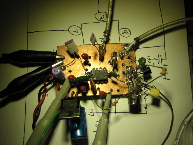
simultaneously to Frequency demodulation . I built up a simple double sided etch
PC board and made an operational circuit , the FM loop capacitor was a 470
pf bypass and the AM detector was .01 uf , the v+ rail
was 6 volts via a 3 terminal regulator . The VCO was set to 455 Khz and
the fm audio output was connected to my usual amplified computer speakers
, these are not the most sensitive audio amp but 10's of millivolts
of audio input yield audio loud enough to hear on the work bench .
I connected the 50 ohm source from the signal generator directly to the
capacitor input of the NE567 , this is a rather large mismatch as the input
impedance of the 567 is 25 k ohms ( more about this later) I
connected the audio amp input to the Demodulated fm output pin 1 , and punched
up 455 Khz , FM , 2.5Khz Dev at 1 Khz tone , and then ramped the RF output
amplitude up from -100 dbm until I heard sound from the speakers ..
I tested the PLL at 5 KHz and 2.5 KHz deviation, and measured the audio output level with the oscilliscope in high impedence (~1 meg ) mode . The NE567 requires a minimum of -35 dBm across 50 ohms to achieve reliable lock .. I noticed the value of the filter capacitor has an influence on the broadband noise appearing from that pin (2) ,in this test I had a 470 Pf , I noticed the rise in apparent level on the oscilloscope, with increases in the input level for FM it should remain the same , but I suspect not having an adequate low pass audio filter network , allowed the broadband noise to increase . subjectively I did not detect and increase in the loudness of the demodulated signal as the input level stepped up ..
Input Level 5.0 Khz 2.5 Khz
-35 dBm 58 mV 29 mV
-30 59 31
-25 62 32
-20 64 35
-15 66 36
-10 67 37
-5 72 40
As a matter of interest I connected the input to the NE567 pll to the tracking output of the spectrum Analyser ( at -20 dbm) and connected to the input of the analyser a capacity probe placed very close to the VCO components to look at the VCO frequency , I manually adjusted the VCO pot ( 4K7) for maximum frequency and looked at the flat plateau ( lock range) on the screen this NE567 at +6v rail would go to a centre frequency of 1200Khz and sweep +/- 350 Khz . considerably higher than the 500 Khz advertised in the data sheet !
The next test was 455 Khz ,1 Khz tone , AM 80% modulation over a range of input levels and look at the audio output level from the synchronous demodulator (pin 1 )
-40 dBm 44 mV
-35 77 Clean sounding and looks correct on scope
-30 130
-25 233
-20 320
-15 350 1 Khz tone starting to sound slightly distorted
-10 305 sine wave shows distortion and sounds it
-5 195 sine wave shows more distortion and sounds worse
There is quite a wide dynamic range over which the synch
demodulation sounds very clean and in a normal radio receiver the
levels would be chosen to be held by the AGC in the receiver
There is a large mismatch between the 50 ohm signal source at 455 KHz amd the 25Kohm input impedance of the ne567 , I placed an interstage transformer in the circuit with the low impedance ends connected and the top of the tuned circuit to the capacitively coupled pin 3 , this enables a more sensitive PLL and it will lock at lower levels due to the increase in voltage derived via the 455 Khz tuned circuit input . However when connected to the 455 Khz IF tap out of the scanner , I found I required more voltage gain than the tuned interstage coupling transformer could provide, so a single transistor bc547, class A stage was lashed up and connected to the transformer input . .This enabled good reliable clear demodulation of both modes at the -70 dBm scanner 455 KHz output .
Listening test ;
The 455 Khz of the AOR2001 scanner was connected to the PLL demod and both forms of modulation listened to off air from air traffic control (AM) and local police ( nbfm ) the demodulated audio of the weather broadcast on 128.800MHz AM was clear and clean sounding , the nbfm was also clear and clean , but to do the setup justice the signal really needs to be fed via some sort of AGC control in the receiver ,to keep the ne567 in the middle of its"happy "range
The NE567 as a tone decoder is a more versatile device than first meets the eye . I have not had a look at the xr2211 PLL chip but I gather that chip is obsolete ..
Hope my findings are of use to someone or promotes some new idea
cheers Mike ZL1BTB