Motor Cycle Antenna for APRS on 2m
After having APRS on 144.575 Mhz, the VHF allocation
for the mode in New Zealand, for some time in my car,(ZL1BTB-10) I decided it would be nice
to try it on my motorcycle, ( ZL1BTB-9) so I looked around to see what I have available , I
used a tiny track 3plus APRS modem from Byonics , a junk sale
purchased GPS unit with rs232 @ 4800 baud .12 v DC , and a FDC
Chinese brand small vhf hand held radio that covered the
amateur radio frequencies we use here in New Zealand , The radio had a
switch able RF output of 0.5 and 5 watts . The radio had its own battery
pack but I opted to use a small switched mode 12v battery eliminator
designed to clip onto the back of the radio in place of the battery as i have
had the radio go flat on long rides ,, The
battery eliminator had a male cigarette plug on it so I connected a female
socket directly to the 12 v battery of the motorcycle ;
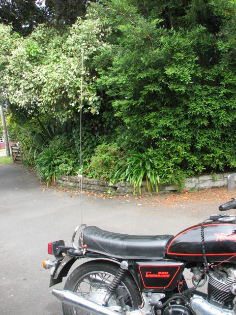
I decided to use a quarter wave ground plane on the rear
right hand side of the bike and fed with RG58 50 ohm coax terminated in a
BNC cable at the user end , The system was assembled , tried and
did work to a limited extent ,I could be seen riding around the city with
quite good accuracy and providing a nice track on the APRS.Fi .com website .
However I did have an intermittent problem with the Tiny Track 3 locking
up after a while . At first I thought it was RF getting into the modem
causing lock up etc I tried rf bypassing , ferrite chokes , positioning
of the coax , modem ,radio and rider , but to no avail. The small 3 terminal
voltage regulator was coming to hot to touch and switching the TT3 off
. It
was eventually traced to the voltage supply on my 1973 Norton commando battery
charging supply being too higher voltage , most old British motorcycles have a
very simple voltage regulating system ,the rectified DC from the
motorcycle alternator is clamped at 15 v by a big grunty 50W Zener diode to prevent
the battery getting over charged ??? this high voltage was
proving too much and the tiny 3 terminal regulator in the tiny track 3 was going haywire
. I ended up by running the modem and gps off a small 12v gel cell and have never had a problem
since ,its a little bit of a nuisance but I can live with it as it works
well.
I was never happy with the RF performance of the quarter wave set up and 5 W . I felt it should perform better than it did .Now I know a motorcycle frame is not exactly a substantial ground even at 2 m and with the rider bolt upright ahead of the antenna , shielding 180 degrees of radiation ( assuming it was omni directional ) it just did not perform as I would have liked . The next was to try a 5/8 wavelength vertical mounted in the same position . So one was made up and I even spent much time tuning and matching using my Agilent 5062A VNA . Although much better than the quarter wave I felt it still should perform better than it did . (Given my previous experience with 5/8 whip antennas) . It just shows to show you despite excellent rf matching to an antenna , if other parameters are not taken into account ( ground plane etc ) it can still operate like a piece of wet string ....
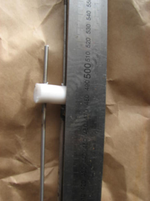
After some thought on the matter, I figured the motorcycle frame was insufficient to allow the ground plane dependant antennas to operate efficiently, so I did some internet research on ground plane independent antennas, This harked back to the old standard vertical dipole . That is what I needed. Centre feeding it was put in the too hard basket ,so it looked like endfeeding was the way to go. All I had to do was match the 50 ohm unbalanced feed to the balanced dipole antenna high impedance end , Now this can be done several ways ,i.e tapped tuned resonant circuits feeding one end of the high impedance point . easily done but can become a little bit of a mechanical nightmare , hiding away tuned circuits and capacitors from the elements and holding the 38 inch stainless tapered whip by the base as well and then attaching the whole lot to the frame . I figured the easiest and probably most robust system to build was an end fed Zepp for 2m , Now the ubiquitous " J pole " of UK fame is based on the configuration . Non radiating quarter wave stub as an impedance match , feeding the high impedance end of a resonant dipole , so I looked up the usual rf equations for antenna construction and made up a half wave on 144.575 MHz, fed with a quarter wave stub , all made of stainless steel and brazed onto the screw on antenna base to mount it to the motorcycle frame. The usual 19.5 "tuned lines and 39" whip brazed together . when it was finished it looked exactly like a J pole but I didn't fold over the dipole radiator as bandwidth was not an issue but wind resistance was ... !
I soldered the coax feed to the appropriate points up from the base of the stainless steel antenna using commercial Duzal acid based (Zinc chloride ) soldering flux ' and adjusted thus to achieve a good low swr match as shown on the Agilent 5062A , (overkill I know , but since I have it .its just as easy to use it,) I went for a ride on the bike to try the performance of the new antenna. Things went great , until I came to the first corner when apon rounding, the bike engine cut out briefly , restarted only to let out a loud backfire , It wasnt until quite a few corners later did I realise it was RF getting into the non sophisticated electronic ignition ( Boyer Brand) . Every time I went around a corner the tiny track would send a data position to the radio and the resultant rf packet killed the ignition briefly . Then of course it came back on when the RF stopped , muffler full of unburned gasses ...boom !! . Id never had this on the bike before, even when running HF mobile 10W ; RF getting into the wiring !, I repositioned the coax ,still did it! , Changed radio position on the tank , High power? , it still did it .Then switched to low power and it minimized it . So i stopped and thought , RF on the coax ??, it has to be ! so I looked at the antenna , its a tuned ( balanced line feeding a balanced antenna ) system , therefore it should have a balun to keep RF flowing down the outside of the coax and radiating in to the bike wiring , now if anyone tells you a J pole does not require a balun, I will challenge that statement from first principles .
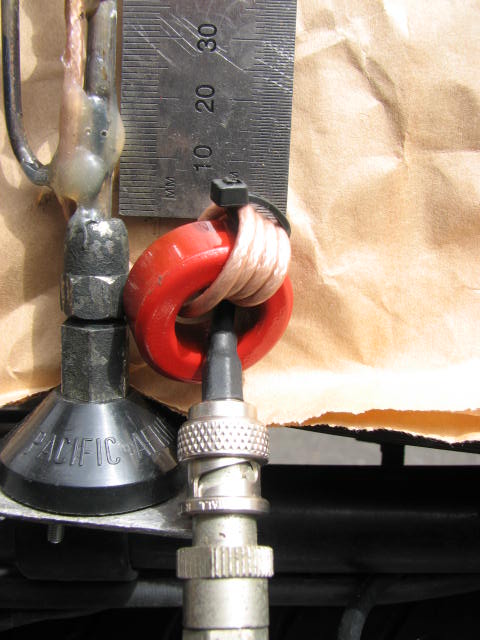
A simple 1:1 current balun was constructed using a
small red t series amidon core of 25 mm O.D and with 5 turns of
rg174 ( teflon) coax tightly close wound and held with a cable tie. This
coax was connected to the matching points on the base of the antenna . Off
for a ride , and no backfires!! I went for my usual ride out to the local
lakes and back and noticed immediately a much better APRS.fi.com track on the
computer , with "hits" on just about all the corners of the route
. This
was not happening with the previous quarter wave or 5/8 wave antenna
,
When you mount your j pole . never electrically connect it to
the frame or pipe supporting it . In fact if you
can ...have some sort of insulating medium separating it up some
inches from the metal mount . If you connect the base of the j pole
to the metal mounting pipe, the induced RF currents from the end of
the parallel matching section will induce Rf into the metal pole and
your radiation pattern will go skew wiff and deviate from the
hopefully somewhat doughnut pattern of a vertical dipole and you will loose
antenna gain .. ..
I have been using it for quite some time now and with much better
results all round . The 19" tuned line puts the base of the 2m
dipole up high above the bike and less of it is shielded by the rider ,
the rider being somewhat ahead of the whip shields it from a lot of wind
and it tends to stay upright than bend back ( thats why I didnt opt for J
pole configuration the folded whip is higher wind resistance and will bend back
from the vertical.
,The simple 2 m dipole antenna is probably the most gain antenna your going to get on a motorcycle , so i don't think I can really improve on its performance.... its working well so ill leave it and keep it simple . try it you'll like it !!
click to return to HOME PAGE