Mini Circuits Low Pass filters.... SMD
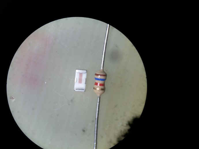
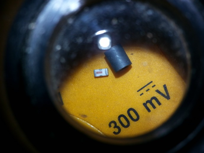
I required a low pass filter to insert into a small low power commercial radio transciever contained in a Earmuff style headset . The radio was in the 420-480 MHz range , but the attenuation of the secaond harmonic at 800 odd MHz was no where near commercial requirements . It had to have a lowpass filter added to the antenna feed line to be even " in with a chance" . I sat down with the PC and a filter design program and drew one up a circuit . fired up the soldering iron and got to work .. I didnt like the way it performed on the VNA and I didnt really have a lot of room in the ear-cup of the headset boom mic radio either and it had to be small ..and perform . , too much ripple and too much loss!! I fiddles as much as I could to make it as small as possible but to no avail .the too hard basket !!. . So I went on line to search minicircuits http://www.minicircuits.com/products/Filters.shtml who I know have for some time, produced small RF filters of many types. Lo and behold ,they now produce a SMD version as well as the usual SMA ,.plug in and BNC connectored ones . I went to the data catalogue and selected the low pass one I needed , LFCN 490 and them ordered some from their outlet in Australia . ( try minikits as well, they are cheaper all round ) ..wish I had known that before !! They turned up and boy are they small . impressive performance in a small package and they will pass up to 8 W of rf .. tThey are so tiny , look at these pictures below : The rf goes in and out of the ends and if you look closely you can see the earth connections to the left and right of the brown line on the filter .. The filter exhibits about 1 ohm through dc resistance and the two earth connections are connected together and exibit a short circuit.
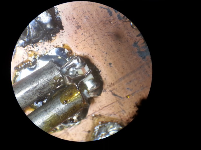
I had to make a tiny test jig to try them out so i used small copper 50 ohm hard line soldered to a scrap of double sided copper laminate
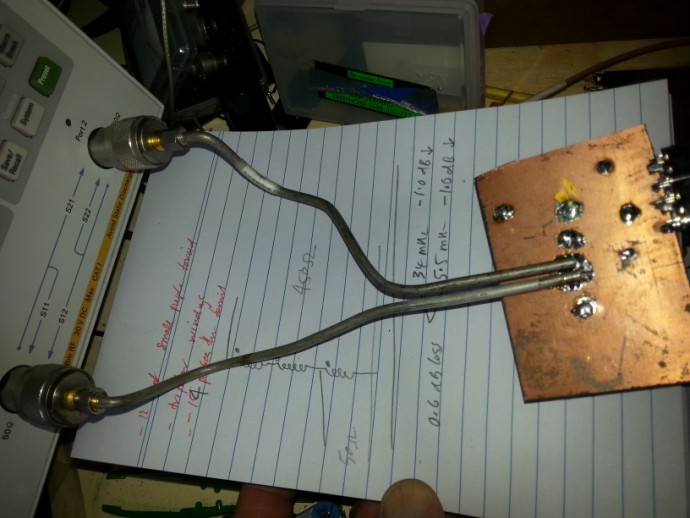
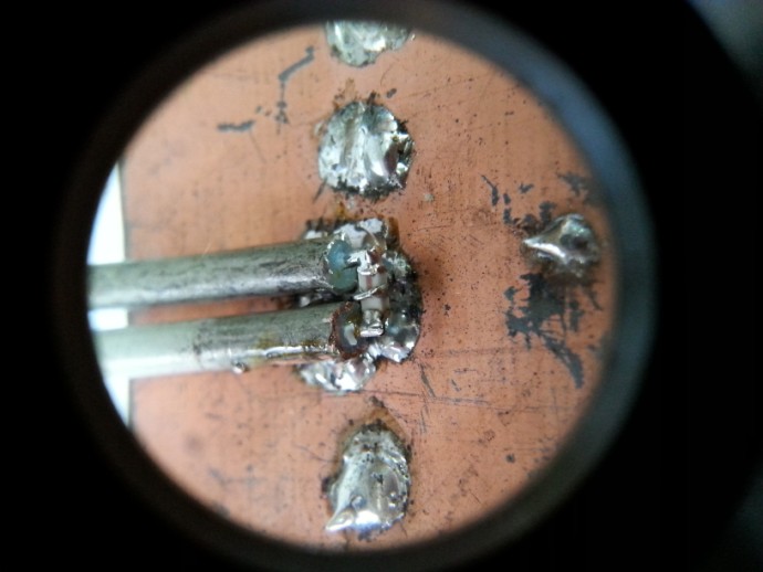
Look carefully at the close up of the test jig and you can just make out the
SMD filter , I constructed a small U shaped piece of wire soldered to the
middle of the filter as the common earth connection . Be
really careful with the earth connection and make sure it is very low
inductance if you wish to have specified Rf performance in this case , to 1 GHz or more
.. see following displays
long ëarth
connection solder blob "
Short earth connection to copper of feedline
sweep with high inductance earth connection
Short earthed connection sweep
you can see the huge difference in RF performance by simply by having a really low impedance to a common earth ...the filter works! me thinks that was the problem with my design and test build . leads too long hence ripples and poor performance .
The next headache was inserting it in series with the miniature 50 ohm connector feedline thank good I have a stereo microscope to help with my old failing eyes !
Over 300 models in stock for a wide range of applications from DC to 15 GHz!
look in here http://www.minicircuits.com/products/Filters.shtml
http://www.minikits.com.au/components/mini-circuits/mini-circuits-ceramic-filters in Australia and much cheaper all round