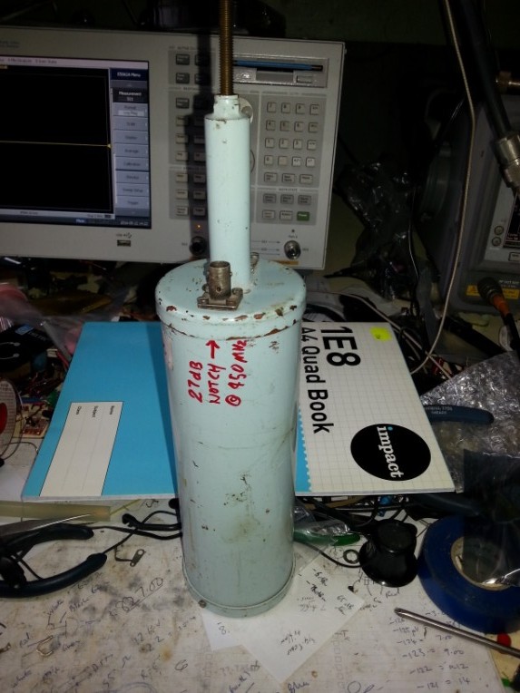
Measuring second harmonic level via notching the fundamental frequency
I wanted to measure the second harmonic of a small I watt UHF
transceiver using the spectrum analyser . I wanted to be sure that the
attenuated input fundamental signal on 433 Mhz and another separate radio on 409
.75 Mhz, was not going to affect the linearity of the front end mixer in the
E4407 spectrum analyser and give an erroneous measurement of the second harmonic
at 800 odd MHz.
The analyser is always preceeded by a very large 500 W 30 db Bird power
attenuator to protect the front end and ensure linearity, in that may improve
the dynamic range of measurements of both milliwatt signals concurrently but was
unsure of any interaction. So i decided to try to reduce the fundamental carrier
to the input while trying not to interfere with the actual level of the second
harmonic .
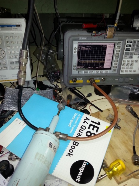
I was somewhat familiar with coaxial resonators so decided I would create an RF notch on the unwanted carrier frequency to try and reduce its possible affect on mixer linearity thus on measurement accuracy , I had a couple of small UHF coaxial resonators with coupling loops cofigured as a simple bandpass . so I set up the filter with a T connector on only one port and connected to the network analyser, I reduced the span to look closely at the result , the depth was barely 10 dB , not enough coupling inside the cavity ! so I pulled one of the coupling loops out and increased the size and length of the loop and tried again , After a bit of fiddling I achieved around 25 dB depending on how you held your tongue, wiggled cables connectors etc .. That was enough of a notch depth as that would remove a fair bit of RF at the fundamental carrier frequency.
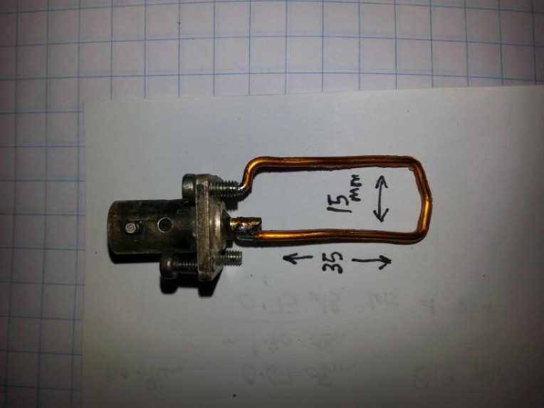
two port uhf filter enlarged coupling loop measure 409 MHz attenuation notch
I measured the small transceiver output power at both
fundamental -0.9 dBm ( +29.1 dBm) and second harmonic .-31.5 dBm ( -1.5
dBm)
Please note that at most times, there is a 30dB attenuation ahead of the
analyser so you will have to mentally add -30 db to allow for this rf protection
attenuation, to have the graphs and figures make sense . I have some radios I
have installed with minicircuit ceramic 7 pole low pass filters,LFCN
490, I have installed at the rf output and some identical radios
that have no output filtering at all .The basic radio output can be seen on the
plots, the radios with the minicircuits monolithic filter exhibit a dB or more
loss the RF output . I am aiming to achieve a radio transmitter with a second
harmonic level better than -26 dBm as required by govnt regulations here in NZ.
notch response at 409 MHz notch absorption
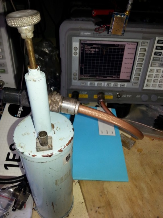
I measured the insertion loss of the 409/433 Mhz tunable notch filter which worked out to be about 0.7 dB at 819 MHz /866. Mhz I did terminate the open coupling loop with a 50 ohm termination and found it made no measurable difference to the insertioin loss at the 800 Mhz second harmonic frequencies, I guess the filter is operating as a half wave up there , so is very high impedance to them ,however addition of the 50 ohm termination caused an appreciable change in frequency and notch depth at the 400 Mhz frequencies. With the second loop coupling left unterminated the notch depth was around 24.9 dB however with the 50 ohm termination and a retune to maximise performance , the loaded notch depth it was only 17.4 dB deep .I guess you would have to use this port loaded technique if you were testing a high power transmitter eg tens of watts, by using a suitably rated 50 ohm load to dissipate the diverted notched power ???
RF output into spec An at fundamental after being
notched out
Out of curiosity ,I decided to see how much rf was appearing at the terminated second coupling loop, so disconnected the spec an from the through T connector and placed it on the scond coupling loop. I put the 50 ohm termination on the through T connector which we know had -26.8 appearing . On the 409 Mhz frequency there was -8.5 dBm available and -18.8 dBm out of the through T connector .though it was comforting to know one can use a resonant notch to reduce the fundamental carrier level and thus try to minimise the potential high level fundamental frequency influence on the rf mixer stage to see the true level of the second harmonic. Particularly when it was greater than 80 db below the funamental in a transmitter with a very good low pass filter on the output .
using the Notch to "enhance" second harmonic after minicircuits low pass filter
At the milliwatt power levels I was experimenting with ,the dynamic range of the e4407 can encompass accurate readings of fundamental and second harmonic simultaneously from a transmitter with a low pass filtered output , but the dynamic range of the HP8920 test set in Spec An mode would really benefit the use of the fundamantal notching technique to maximize mixer linearity, if one wishes to obtain an accurate second harmonic level .
well i hope this little experiment is of use to someone else and if you can see any errors in my methods please drop me an email
cheers Mike ZL1BTB