Super regenerative receiver quench investigation AM to FM ?
By
M Pinfold ZL1BTB
I was investigating super regenerative
receivers by looking through the patents on the web when I came
across a patent for a super regen that can demodulate NBFM ,
We
all know super regens can demodulate AM and they slope detect WBFM
but they cant effectively demodulate NBFM without super careful of adjustment
of quench frequencies and the waveform shape . Neal brown was granted a
patent US3337807A on 29 Aug 1967 for super regenerative
amplifier detector to which he added a fm demodulator to demodulate the quench
frequency .
If you look it up on the web you can read all about it
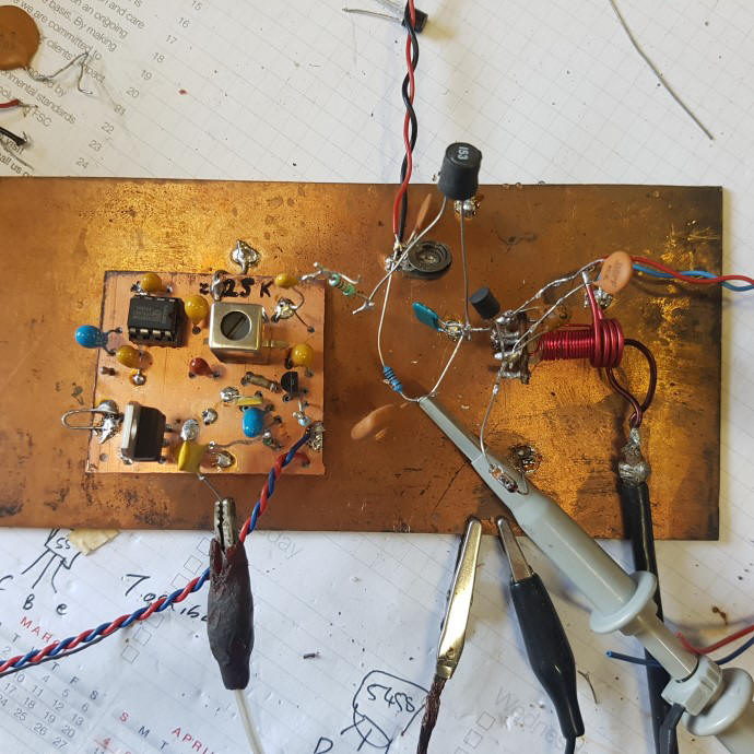
test setup ,polyakov basic super regen self quenched with Quad demod board connected
So I decided to investigate the claims of the Patent , I decided to use a PLL tone decoder as an FM demodulator running at nominally a quench frequency of 20 Khz , having had previous experience with NE567 as an FM AM demodulator at 455 Khz .. 20 Khz is achieved with a 4K7 variable resistor and a timing capacitor of 0.039 mfd .
I decided to make a self quenched super regen at around 25 Mhz using a grounded gate J310 Jfet oscillator configuration , I tuned the quench to be at about 20 Khz using the trim pot across the quench capacitor . I fed the unbypassed audio along with the quench frequency directly into the ne567 with its pll osc trimmed to about 20 Khz and picked off the audio out of the FM or AM pins of the NE567 and fed it to my bench top amplified speaker .
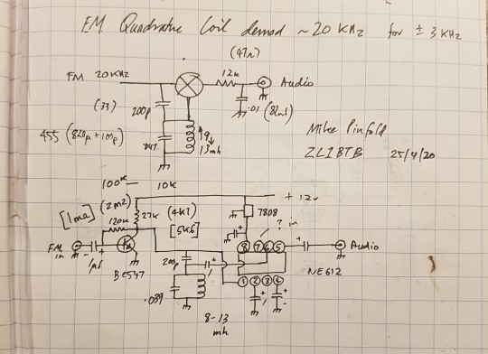
20 kHZ
QUADRATURE DEMOD Circuit diagram
I used an Agilent signal generator as the signal source for the super regen detector , AM was a 1Khz tone at 80% mod and FM 1 Khz at 3KHz deviation for NBFM
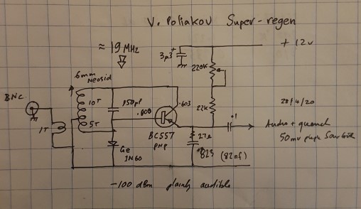
circuit of poliakov super regen
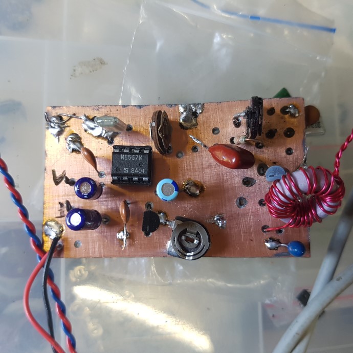
NE567 PLL as AM/FM demodulator with grounded gate super regen at 25 MHz
I
did have a play with the regeneration and quench frequency pots as
there is a lot of interaction between them to optimise demodulation
.I was able to monitor audio directly from the receiver itself and to compare it to that demodulated via the
NE567 ,
With
careful adjustment you can demodulate 3 Khz deviation NBFM and
listen directly but it is very fiddly to achieve and im not sure if
the oscillator is still operating in the normal quenched mode
The
recovered A.M audio level from the NE567 fm detector is much
much louder than the direct demodulated audio from the super
regenerative detector , direct level was xxx mV verses yyy mV
of demodulated AM via the FM detector . (Yet to measure)
Neal
brown did make the comment that the modulation of received signal is
impressed onto the quench frequency in the super regenerative mode
and this appears to happen ' So to check my measurements, I also built
up a standard quadrature FM demodulator tuned for 20 Khz ,preceded by
a single untuned amplifier stage , I fed the unbypassed quench
frequency into this demodulator and received the same result as the
NE567 , the large audio improvement demodulating the approx 20
Khz quench frequency
I looked at the quench frequency with an oscilloscope connected to the top of the quench capacitor with and without AM modulation
RF Input -60 dBm
no
modulation to the 25 MHz rf signal
note
the displacement of the 20KHz quench frequency with 80% AM
modulation
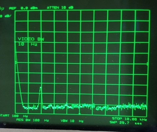
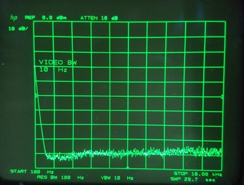
There is definately deviation of the quench frequency with AM modulation so I decided to feed the quench frequency into the spectrum analyser to confirm the presence of quench waveform modulation , this is what I saw without and with 80% AM modulation 1 Khz tone .
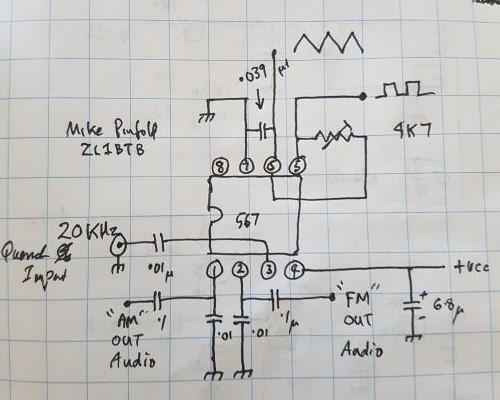
NE567 PLL Decoder for AM/FM at 20 KHz
Just 25MHz carrier only and no
modulation seen on 20 Khz quench frequency
25MHz 1KHz 80% AM into receiver, 20.93 KHz quench now showing characteristic FM display
so it appears that the AM received modulation
definitely ends up by frequency modulating the quench waveform .
Hence the excellent audio output level from the quench fm
demodulator when compared to the “normally detected”
audio output
As
a matter of interest the best sensitivity was hearing the 80%
modulated test tone very noisey at -100 dBm ….. 2.24 uV in a
50 ohm system without an rf preamp ahead of the superregen. Going to
try an rf preamp to see if I can improve this sensitivity figure and
also isolate the oscillations from radiating out the antenna
I
will next try an Externally quenched super regenerative receiver
where I will use the same NE567 AM/FM decoder circuit for detection
,but I will use the square/triange wave form from the 20 Khz NE567
VCO to gate the rf oscillator in and out off “quenching”
and see if the synchronous detection capability of that setup enables
modulation to be achieved .
I
noticed a potential problem for FM demodulators in super regen
receivers that are self quenched is that the quench frequency varies
with rf amplitude and regeneration voltage , so a fixed frequency
demodulator like a quadrature form ,will not cope with quench
frequency drift , the PLL can cope over a wider range , so I decided
to try a pulse counting FM demodulator since the quench frequency can
be down around 20 Khz or so where this type of demodulator can give a
good level of audio output because of the large ratio of change in
pulse width to carrier frequency . There are a number of pulse count
demodulator circuits on the internet most of them incorporated in
domestic band wbfm receivers , where the demodulated Intermediate
frequency is between 200 KHz and 80 KHz . For WBFM at 75 Khz
deviation the down converted 200 to 80 Khz I.F. ( depending on the
design) Gives good signal to noise and fidelity response .The fact
that the quench frequency may wander around somewhat doesnt make a
huge difference to the demodulated audio level .
I built up a
simple 2 transistor circuit copied from the web (vk2zay and others )
of a limiter and a pulse counting ( integrating) Monostable the
output of which is sent the a low pass filter to obtain the wanted
audio
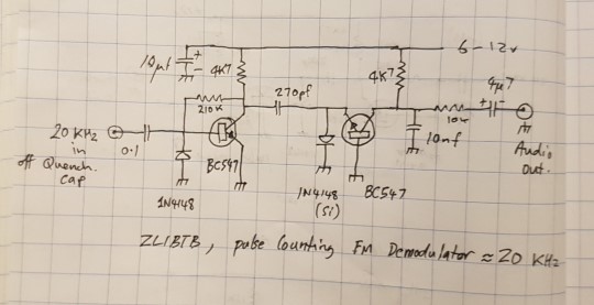
circuit of pulse counting FM demodulator
What
I did for my circuit that operates at a lower frequency , was to
multiply the critical components like the capacitors by the scaling
factor of I.F frequency eg 200 divided by my circuit frequency of
20 ie ratio of 10 ... so 50 pf at 200 Khz becomes 500 pF at 20 Khz
. Optimally the monostable should really have two stages of I.F
amplification ahead of it , but since I was not going for fidelity
here ,I only used one to test the principle .. well it worked .
The super regen I tested it on had a quench amplitude of about 300 mV
,so that was a resonable quench level to start with , I got the
“pulse counting” circuit going and played around with
component values to optimise the simple circuit I had .
The
recovered audio was very good and light years ahead of the usual
source of audio in the super regen I was using , I put this down to
the efficiency of the FM demodulation process rather that the usual
envelope detection process to obtain recovered audio .
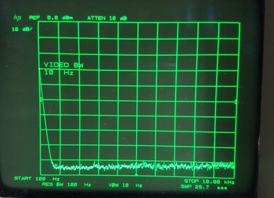
I suspect the performance of the super regenerative detector gets let down by the audio chain after it I suspect the high amplitude of the quench frequency plays havoc with the audio chain , perhaps a well performing low pass filter, active or passive is required at the demodulated output . What makes me think this is the spectrum analyser sweep of the audio output of the poliakov receiver from 100 Hz to 10kHz .This shows the RF test signal of -100 dBm at 10.96 MHz, modulated with a tone of 2Khz with very good signal to noise ratio. !!
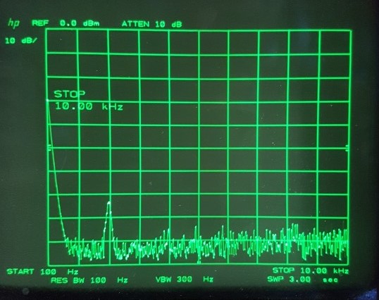
-100 dbm RF signal 2KHz tone
into super regen (spec an looking at AUDIO output)
This
a reasonable signal that should sound clearer than it does I will
try a better low pass filter to see if I can get rid of the
extraneous noise and improve acoustic performance I
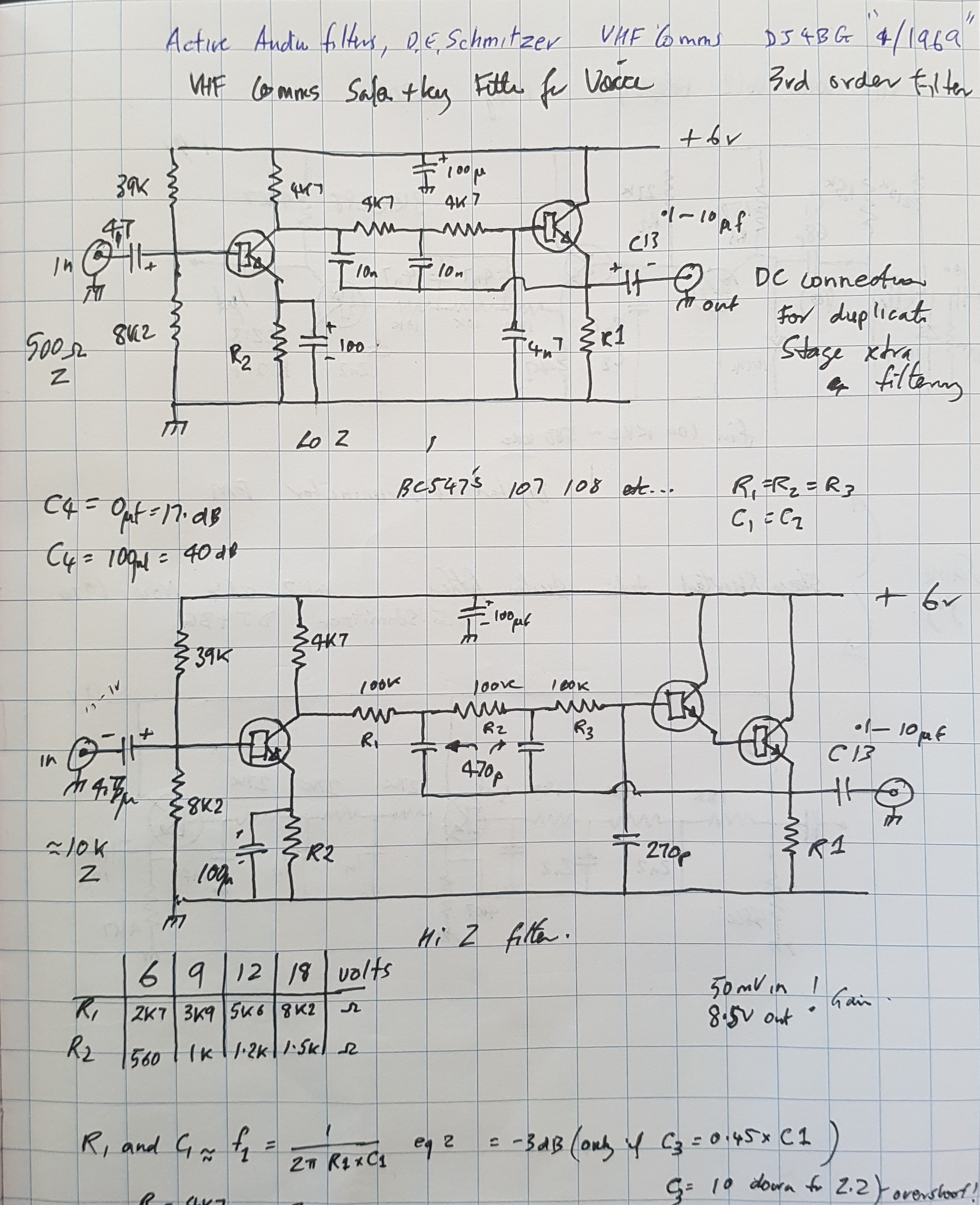
had built up some time ago a third order low pass active filter of
the sallen and Key, the circuit from VHF Comms 4/1969 “Active
audio Filters D.E Schmitzer DJ4BG so I pressed it into service ,it
rolled off sharply above 3 Khz it worked extremely well and it
enabled me to now make s/n measurements with a S/N meter
-100 dBm rf signal
spec an looking at demodulated output
RF off
no modulation …... note noise level increase
!
The receiver is building up from random noise there is no coherent signal to replace the noise so random noise predominates ??
-100
dbm RF, no modulation , note
some quieting as base noise level drops
This could correlate with the receiver spending slightly less time building up from random noise as there is now some coherent rf stimulating oscillations in the tuned circuit hence less noise is seen.????