Duplexer for High Frequency Repeater
The building of an experimental high frequency repeater
made from two Codan transceivers for SSB required implementation of a much
improved isolation between the transmit and receive antenna .
I was using two hf antennas separated by 100 m and both antennas being end
on for maximum isolation but the interferance from insufficent separation
was still too much
I decided to build a set of narrow band filters ,one for
transmit and one for receive to minimise the interaction . since the
very low frequencies precluded the use of cavity resonators, they would be a
quartter wavelength at 4.8 MHz, a lumped
inductance helical system is the only option . I have some shareware
( helical.exe) that
will produce the dimensions for boxed helical resonators so after
much reading up on the subject I went to work . I decided to use coils 160mm in
diameter ( bigger would be better .). and the cheapest and easier was plastic
biscuit barrels under a brand "Click Clack" They had a
substantilly fitting sealed lid by which I could attach them inside the
aluminium box cavity and thus facilitate easy removal of the whole
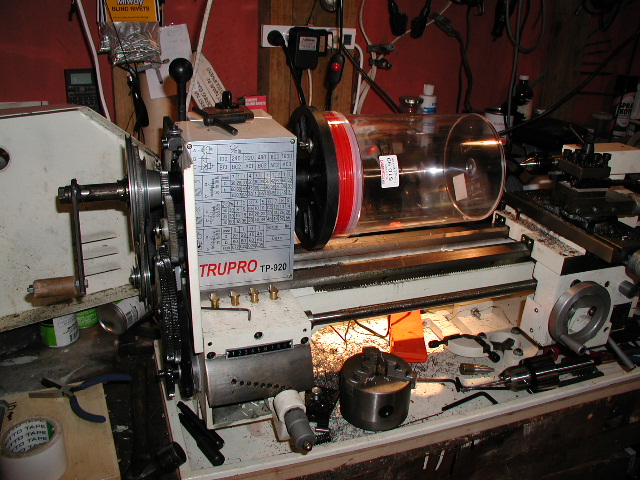
assembly . I decided it was easier to wind these on the small metal lathe I
owned. I ran the shareware and arrived and dimensions .
I fabricated a handle to hand wind this gave me a little more control doing it solo I used 1mm dia enamelled copper wire and some plastic coated hook up wire as a spacer to hold the turns
![]()
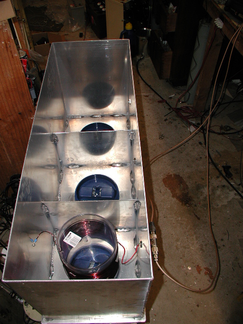
The two fabricated aluminium boxes were tig welded together forming 3 chambers into which helicals were mounted by the lid of the biscuit barrel screwed to the floor of the cavity . Note I ran my cavities upside down i.e. the hot end of the coils were in the depth of the chamber this was an attempt to minimize capacitive effects when playing with coupling systems etc hand capaciance .. see I started winding the coils 1/3 way up the biscuit barrel ..the cold end ( earthed and coupled will be at the top .
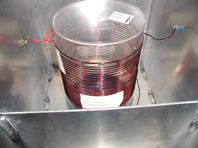
The helical barrel was plugged into the secured biscuit barrel lid, the cold end of the coil sucurely attached by a good low impenance connection to the inside of the compartment , the helical was tapped to the outside world 2 turns up fron cold end and then connected to the tracking generator via 30 ohm coax . The filter was ttuned to the wanted HF Frequncy eg 5190 Khz
by chopping of turns and leaving a wire spike free it the hot end this wire could be bent close or away from the walls of the cavity for final tune , dont go too close to the cavity wall or anything more than 25 watts is going to make this wire corona or arc from the high rf voltage at resonance . once I had one helical coil I began to experiment with notches either side of the passband using series capacitence in the tap to the coupling link .
This passbound was acheived with a fixed mica capacitor and a mica compression capacitor in parallel
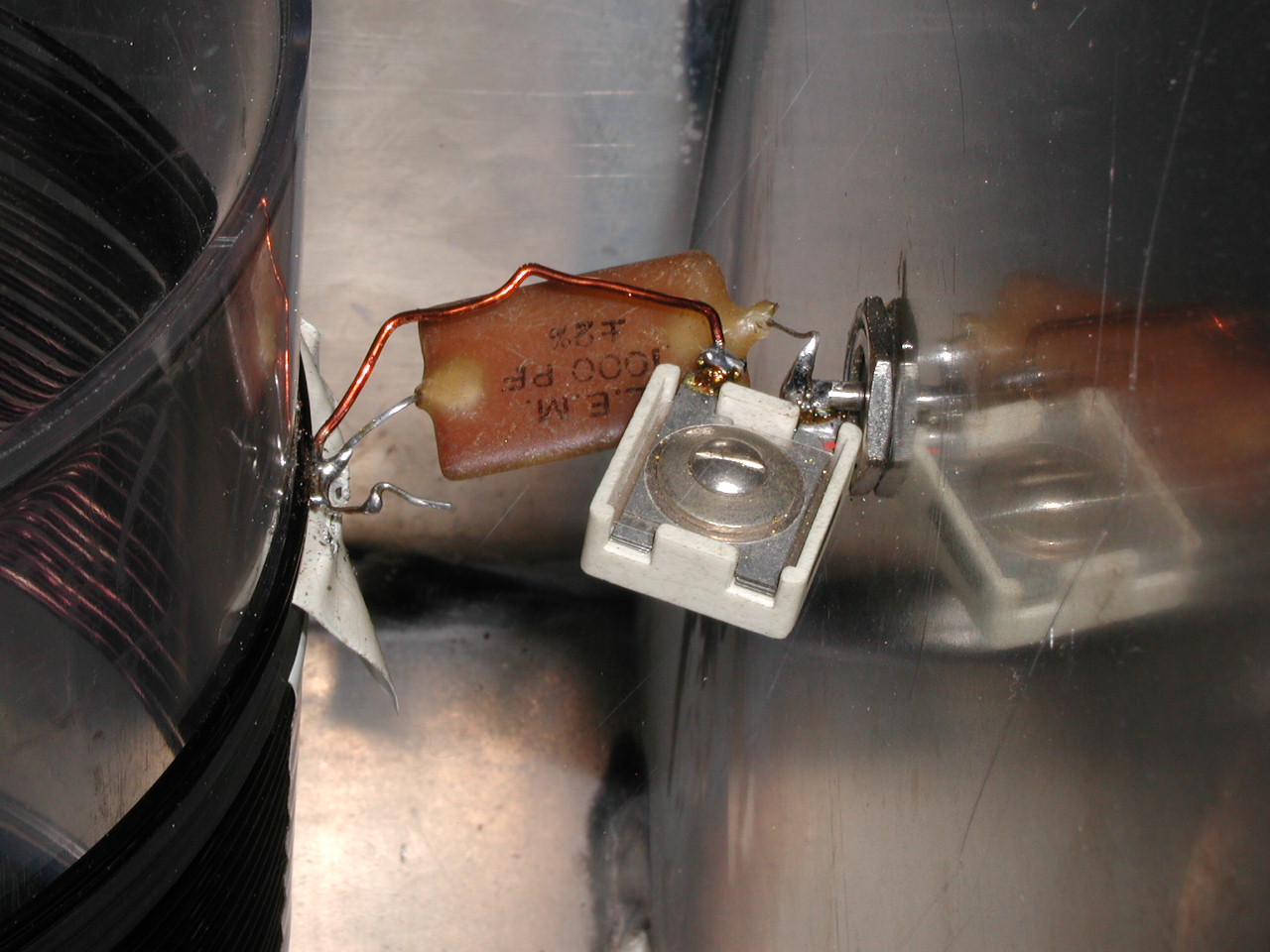
you may notice there is only one photo that shows the
component connection to the tap on the coil a 1000 pf in parallel with a
300 pf trimmer
you can over whlem the inductance of the tap turns less capacitance allows
inductive notch to appear and too much capacitane completely over rides
the inductance to show a capacitance response .
the depth of the notch is related to the "Q" of the resonator and the degree of coupling to the resonator hence it is a balance between great filter performance and RF loss through the filter
The next experiment involved coupling two resonators of
the same passband shape there was no attempt to improve notch depth by
having quarter wave connections between filter as you can do with VHR and
UHF full length duplexers
This is two filters in series with quite good performance
the next step was to go to three coupled helicals with the same bandpass
shape
this is a respectable performance given the depth of the notch 90.4 dB and passband loss just over 1 dB
the 3dB bandwidth of the notch is approximately 30 KHz
I ended up by making a high pass filter and a low pass filter for the transmit and receive frequencies and ran the transmitter at 20 w as I figured that into a full size dipole would provide a good signal .each antenna was connected to the appropriate filter
The system connected did enable corrct operation and my mobile signal did no longer distort and whirl like I was talking from the dark side of the moon ,i suspect the real problem that would show was the temperature stability all in all a sucessful outcome