Originally published in NZ.A.R.T "BREAK IN" Nov 1982
DUNEDIN 2 m LINEAR Repeater
~
Bob SUTTON ZL4DO and MIKE PINFOLD ZL1BTB
The concept of a Linear Transponder is not new. There are many already familiar to us such as the familiar TV translator, the OSCAR series of satellites and the RS series satellites.
Linear "transponders" are repeaters with a difference; there is no signal limiting circuitry and no audio processing. They are, in essence, linear systems where the signals are received, amplified linearly and re-transmitted with no modifications made to the signal except a change in frequency.

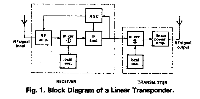
Fig. 1. Block Diagram of a Linear Transponder/Translator.
A close examination of Fig. 1 will reveal how simple the system actually is. A familiar superhet receiver (with AGC) and a transmitter coupled together at the IF stage.
Following the signal path from input to out-put it can be seen that at no point is the signal demodulated.
The lowest frequency is the IF which is then transverted to the output frequency by the second mixer. The receiver has AGC to enable it to handle a wide range of signal strengths and remain in linear operation.
The overall principle is quite straight forward (possibly simpler than
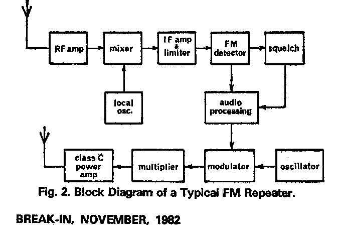
you first thought) and, in fact, simpler than the average FM repeater. Compare Fig. 1 with
Fig. 2.
Fig. 2. Block Diagram of a Typical FM Repeater.
The Dunedin Linear Transponder was built mainly as a technical exercise and to further the home brew spirit of Amateur Radio. The idea had been discussed as a means of defeating Dunedin's big FM and SSB DX killer-Mt Cargill, 2300 feet high at the north end of the city! "Since we can't go over it we'll go around it."
It was decided to construct something operational to spur things along, and the Mk. I version was quickly produced. It was affectionately known as the "Hudsons" because of its resemblance to a small portable FM repeater called the "Griffins" built by Graham ZL4THQ. (Derivations of the names are left to the imagination of the readerl) (biscuit Tins!!!)
The "Hudsons" consisted of a relatively simple superhet receiver with reasonable performance but with a few "lumps in the pass-band. The transmitter output was about 1 watt PEP. A "split" of some 3800kHz between receive and transmit frequencies was used to simplify isolation and to make use of available crystals.(citizens band rocks!) However, even with the wide split, feedback and desensing were major problems.
Much coffee drinking and scrounging in the Flat kitchen of ZL1BTB/4 produced a full length, 6 inch diameter, "Greggs-cafe" cavity filter with passband loss of 1 .2dB and anti resonant notch of 25dB 3.8MHz below the passband frequency. Homebrew spirit indeed!
This filter cured the problems provided that the receive and transmitter aerials were well separated. The success of the simple filter prompted a number of similar models to be constructed by various amateurs to eliminate receiver overload from high powered neighbours.
The Mk. 1 repeater was operated from ZL4DO's QTH which has an excellent hillside view of the city and is far enough south of Mt Cargill to enable some pmpagation of VHF signals around the beast.
The odd mobile SSB contact between ZL1 BTB and ZL4DO at his home station out as far as Seacliffe, proved the linear repeater principle as far as we were concerned.
Work was then started on the Mark 2 version.
After experimentation it was found thatfeedthrough from the transmitter's local oscillator was going to be a real problem to suppress from the output. Various circuits were discussed1 tried and thrown out before we settled ona circuit from a well known VHF multimode transceiver.The now clean transmitter signal was then amplified by a number of linear stages to a final output power of 12 watts PEP. The original Mark I receiver was used in the Mark 2 system but inadequate sensitivity had us seeking a receiver system with better performance-this turned up in the form of a Plessey 615 RT. With minor changes (to coils and capacitors) and re-crystalisation~ the 615's receiver was operating on two metres and up to specification.By-passin9 the original McMurdo plug and the change-over relay gave a 2dB decrease in noise figure. With the audio section disabled (the RF output transistors removed) and an IF output fed to the transmit mixer (via a 30kHz post-IF crystal filter to minimize wide-band noise) the Mark 3 system was bornl
On the test bench this setup worked very well but it was soon evident that our simple isolation filtering was no longer sufficient to prevent feedback problems. Obviously high Q' coaxial cavity filters were required.
The new set of filters for Dunedin 690 FM repeater were imported from the USA for around $1K but, although the import licence
was still valid, another set seemed a Little too much to hope for!
Unfortunately for us the new Dunedin 665FM repeater was put into action with the old
690 filters, but hasn't every Amateur Radio Club a spare set of filters or two put aside for
budding experimenters?
The filters obtained were once used by a benevolent government department on 68 and 78MHz with heavy capacitive loading to reduce their length, thus they were reasonably short. Some modification, via the indispensible mechanical wizadry of Don ZL4TGR, gave us a set of six cavity filters. Many amateurs would not appreciate the complexities of diplexing at 600kHz separation until they need to experiment with coaxial cavity filter Systems. Eventually careful adjustment of the coupling loops and tweaking of the capacitive and inductive "shorts" produced good anti-resonant notches at the right frequencies with acceptable overall passband losses. With three cavities connected for receive and three for transmit, anti-resonant notches in excess of 100dB were achieved in each leg of the filter system.
Modification of these 68-78MHz coaxial filter units will be the subject of a further article to appear in "Break-in"
It was possible to diplex the repeater on to one aerial during experiments but temperature changes are the bugbear of many a diplexed system and ours was no exception!
Even though the Highcliff site has fairly good temperature regulation it was felt safer to retain separate aerials and ensure stable operation. The isolation was so good that a low noise preamp was able to be added bringing the overall sensitivity to a very respectable O.25uV .EMF for a 10dB increase in output power.
Operating through the linear repeater is somewhat different to a FM
repeater. With Dunedin 435 the input frequency is set 600kHz above the receive frequency
and minor discrepancies between stations' output frequencies from the transponder are
compensated by one's own RIT control.More than one QSO can be supported by the linear
repeater simultaneously but the output power is shared by the stations in proportion to
their relative signal strengths at the repeater site. Weak signals may therefore be lost
if strong signals cause the repeater's AGC to come on hard. One must use the minimum
signal into the transponder that is consistant with a clear readable signal out.Perhaps
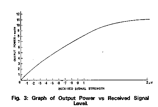
the most curious feature of the linear transponder is that its output power is
proportional to the received signal strength up to the point where the AGC takes full
effect. This is best illustrated by Fig. 3 output power vs received signal level.
Also we think we have the infamous "phantom triggerer" almost beaten . . . the linear has no tail, We have found that the best way to monitor the linear is with your receiver on FM. The wide bandwidth of the FM receiver enables one to monitor a reasonable spectrum and hear most signals coming through.Once a signal is detected the correct mode can be selected and the signal tuned in. A long call is therefore required.
Brief Specifications:
Input Frequency - 144.950 ~ 25kHz.
Output Frequency -144.350 * 25kHz.
Receiver Sensitivity - 0.25uV for 10dB power increase.
Transmitter Power Output - 12 watts PEP maximum.
Location - Highcliff on Otago Peninsula. Thanks to Barry ZL4IP.
Proposed Calling Frequency - 144.350 plus 600kHz USB.
Conclusion:
The transponder in Dunedin is still in its infancy yet signals have been heard as far away as Christchurch and Invercargill. FM signals through the repeater have a peculiarity in that the familiar FM flutter with mute breaking does not occur on weak signals. They appear to hold in more and even come up out of the noise. One gets the impression of less chopped copy and hence greater intelligibility.
Surprisingly, although the transponder noise output is 100mW (39kHz wide), the noise mutes on most transceivers still work well. This appears due to the squelch system of most FM rigs operating on a fall in noise level.
The project has been great fun. There are many future modifications that may still be tried on it. For example, a squelch system to inhibit the broadband noise output when no-one is using the device, a small low power CW identifier for band-opening indication and tone actuated control of the system are proposed.
We would like to thank all those that assisted us in the project from both a technical viewpoint and just plain encouragement.
click and return to HOME PAGE