Direct conversion receiver for 29.6 MHz FM ( still under construction )
M.A.Pinfold ZL1BTB
This is not a concise constructional article as such but a collection of ideas pursued while building up my 29Mhz receiver, hopefully some of the ideas and data found on the web will be of use to those making direction conversion receivers .
Direct
conversion receivers are relatively common and there are several ways
they can be approached .
The simple non image rejecting and the
the image rejecting varieties.
The simplest have a mixer where
the local oscillator is injected at the “same frequency”
of the signal being received and the resulting audio difference (
the wanted signal) is amplified a large number of times to a
suitable listening level .These simple mixing receivers are of the
non image rejecting type and if one tunes around you can tune an
unwanted image response to the signal received . this makes no
difference if your listening to C.W you can still follow the message
, but can cause a problem on ssb usb/lsb where the audio is not understanable
and will require retuning.
.
Image rejection receivers where developed to minimise this unintelligible false tuning interference and this is where the use of dual parallel mixers and injection oscillators of rf injection in quadrature, that create two 90 degree phase shifted channels termed “i” and “q” , come into play . I wont go into details here because there is so much information on the web. By mixing various phase shifted I.F the unwanted sideband can be cancelled and the wanted enhanced .
The
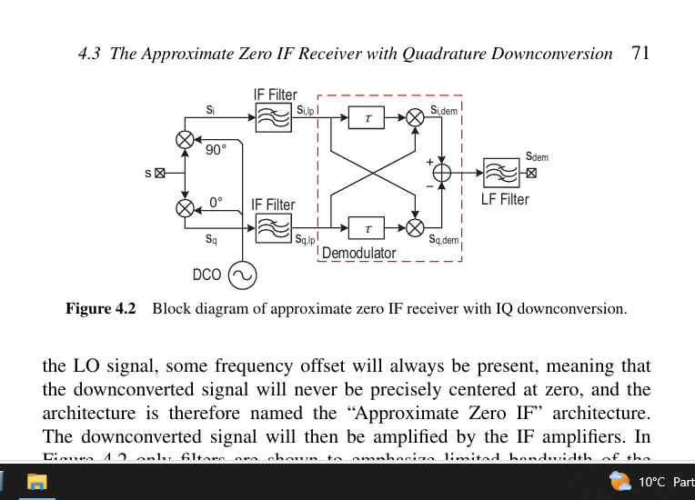
NBFM receiver described here is of the image rejecting type , It is
designed following the “Barber Weaver” method .
The
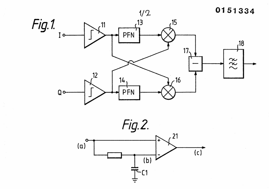
other common way to create a NBFM direct conversion receiver using
“i” and “q” is the sine /cosine demodulation
technique using differential op amps and cross coupled mixers , sometimes
described Havens quadrature circuit,
or quasi correlator demodulation where R-C networks,mixers and adder /subtractors
are configured to do the mathematics to enable the demodulation to audio .
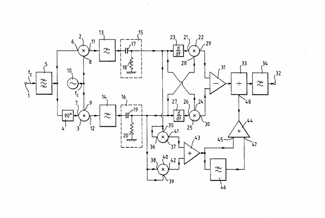
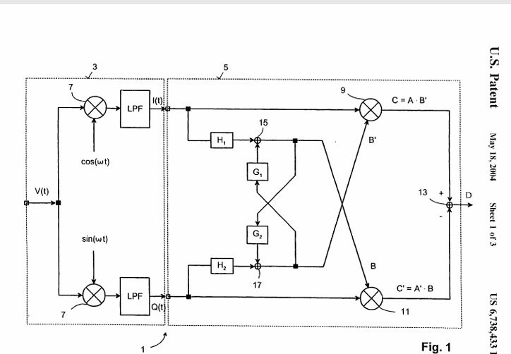
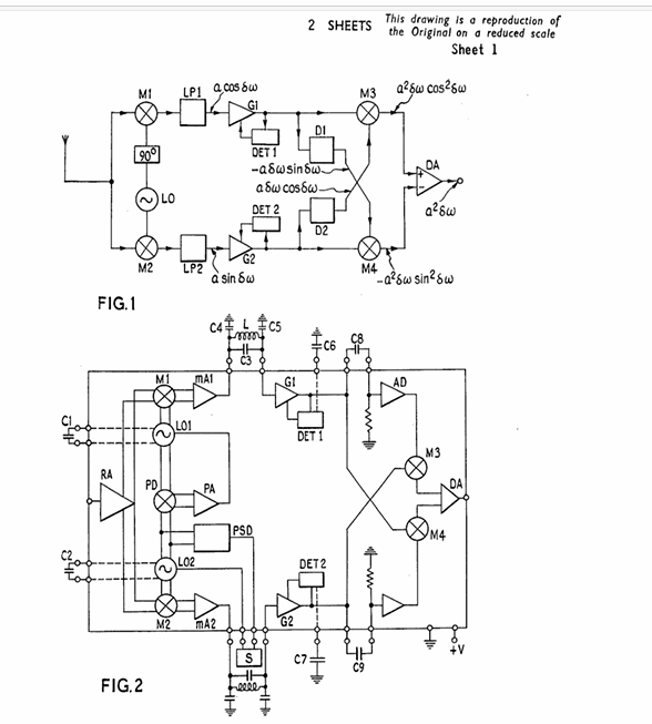
Im sure a lot of you will not really be aware of the above type of direct conversion FM receiver as they are not really common but I have listed some of the patents numbers that confirm a few of them . you can go digging for more, but be careful, browsing patents will give you ideas!! and then youll find you've spent half the day or night on line ... time will fly past ..
Patent Number: Date of Patent: 4,755,761 Jul. 5, 1988 ...... European Patent Office, Publication number: , 0151334.......United States Patent , 3,748,590 11, Gray , July 24, 1973.......United states patent , 4766392, Moore.....United States Patent ,5,414,383 May 9, 1995 Cusden.et al......United States Patent,, US 6,738,433 B1 , Van Waasen et al.........United Staes patent , 4618967 oct 21 1986 I Vance et al.... United States Patent , 3748590 Gray ....... Uk patent application , GB 2351623A , Van Waasen et al .......United States Patent , 3,789,316 , Goetz et al., Jan. 29, 1974.........United States Patent , 3,568,067 ,Jerry G. Williford .... UK Patent 1530602 I Vance 1 nov 1978......
Either of these can of course be configured in software ,however
I will build mine on analogue devices .
The advantage of the
“Barber,Weaver” system is you can hang any
analogue/digital demodulator on the end . For example the front end
of the “Barber Weaver” direct conversion creates “i”
and “q” channels at audio like any other direct
conversion receiver but the amplified and filtered “i”
and “q” channels are remixed independently with 90 and
0 degree phase shifed oscillators derived from the one source e.g
455 Khz and summed to provide “enhanced side band” I.f
output centred at 455 Khz and that 455 Khz demodulator could be for
any suitable wanted mode ..in my case for nbfm using an NE567 ! Or
you could use a quad coil, pulse counting demod , etc etc
I
had a particular constraint, that I wanted to design a receiver
without an RF amp before the mixer so as to keep the 3rd
order intercept up as high as possible and that required a bit of
extra careful design .
Direct conversion receivers rely on audio
amplification to achieve sensitivity ,I will be using Hot Carrier Double
Balanced
mixers eg tak-1, sbl-1, tfm-2, etc these have a conversion loss of
around 6.0 db and thus a noise fig of approx 6 dB
There are of course supposedly lower conversion loss direct conversion mixers such as commutating mixers eg tayloe style which are reputed to be around 3 dB N.F . ?
We
are already at a noise figure of 6db (although thats not high for an
H.F receiver ! ) so we require a very low noise post mixer amplifier
to drag out the weak sub microVolt audio signals and not to add too
much noise to the 6 dB we already have now.
In quadrature systems we have to split RF signals into two equal channels ,so we
can work on them with various techniques , Since my receiver is
fixed frequency the simplist way is to use a Wilkinson Hybrid or splitter
/combiner ,Lots of info on the web so easy to deign and implement .
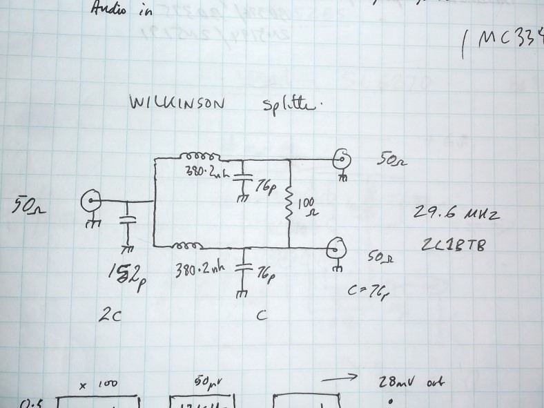
Rf splitter before i and q front end
The other thing we require is a clean
and pure local oscillator source , in my case I will use a crystal
oscillator source at 29 Mhz of sufficient output power to
drive two +23 dBm hot carrier Mixers , each mixer
requires +23 dBm thats 200 mW of Rf ! so your oscillator source must
supply at least 400 mW of RF .
In the Quadrature method we have to split the carrier in two and
shift the two i and q carriers such that they end up with a 90
degrees phase difference between them ,you can do this by two ways
1. phase shift the incoming signals and split it into two equal
parts using a Quadrature Hybrid, the two split RF channals will be
90 degrees out of phase You could do this at the front end of the receiver
before the mixers or
2.split the signal in two but with no phase shift like a wilkinson hybrid
does , and split the two local oscillator signals via a Quadrature hybrid
,or use a digital divider system to generate two local oscillator signals in
quadrature , this latter technique is very accurate and allows for frequency
agility of a tuneable receiver , I dont require that level of
sophistication so I will use the simple fixed frequency quadrature
technique.
You then mix your split RF signal in the mixers with the local oscillator and
you will derive two separate but identical intermediate frequency out puts but with a phase
difference of 90 deg .
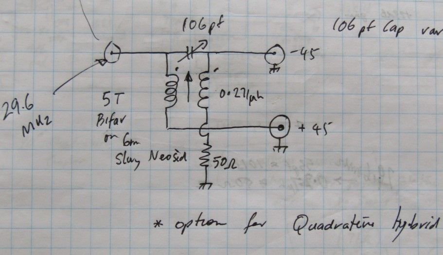
Quad hybride between two H.C Mixers
Schematic of Quadrature hybrid ( one form)
check this out for quadrature hybrids K0JD - Phasing Network Notes for R2 Receiver
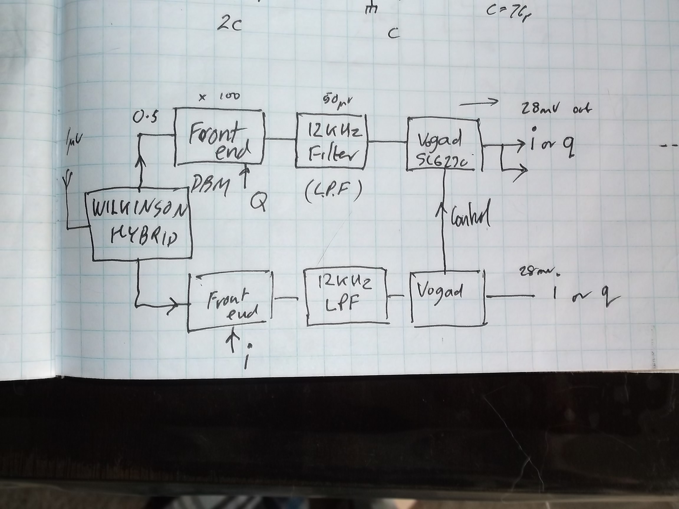
Now we have obtained our two quadrature intermediate frequencies
which in this case go from D.C to maybe 12 Khz ABOVE and BELOW 29 Mhz (as
they will be FM in my case) we have to take them from the fractional
microvolt level up to suitable ampltude to demodulate them effectively. We are
not using an RF amplifier ahead of the Double balanced hot carrier mixers
These have a conversion LOSS of typically 6 db ( could be more
or it could be less ) so now we have set up our receiver to have a 6-7 db
Noise Figure . For a receiver at 29 Mhz thats not too bad
it will put us somewhere close to ambient atmospheric / sky level in a rural
situation, there will be the fractional dB loss in the front end splitter to
add to the N.F as well and dont forget the phase noise contribution of the
29 MHz local oscillator .
To make this receiver perform ,we now have to
amplify our sub microvolt signal by sufficient means to a suitable level in such
a way as to add as little noise as possible
Low
noise amplification
There
are lots of circuit on the web as audio amplifiers for direct
conversion but I felt a lot of them were 'lacking' in low noise
application for use at 29Mhz in an abnormal situation of a receiver
with no RF amplifier .
As in RF applications, its the first signal
amplifier that sets the overall noise figure of the receiver. A lot
of the audio transistors used on the web designs for direct conversion
were not what I would call very low noise audio devices , but given the r.f
environment they will be used in were more than adequate for the job.
In this situation, its the amplifer directly behind the mixer that is going
to try and "maintain" the N.F of the receiver as set by the
fixed losses in the "front
end"
The factors also to
consider is as well as the noise Figure of the receiver, is the noise
contribution of the environment you are
receiving in . If you are on 80m in a semi rural area , the atmospheric
noise is still quite high, maybe well above 10uV level so a super low
noise receiver system is of no advantage at all. You can use a “noisey”
amplifier for that 80m project knowing that it will be able to
"listen below" the level of the general 80 m “sizzle, crash,
crackle”. Picked up by your dipole antenna.
How ever as
you move up in frequency to 10m things change markedly, the level of
"sizzle" falls quite drastically.
Have a look at the ITU graphs for
frequency verses ambient noise in uV for various geographical situations ,https://radarc.org/wp-content/uploads/2021/01/HF-Noise-by-G4JTR-August-2012-RadCom.pdf
this is worth a read .
I now need to be able to
detect a signal at the level of the ambient noise at 29MHz, we are
talking maybe under a uV, in very quiet rurual locations.
You
cant use low noise RF devices in this Audio situation as we are
looking at “audio frequencies” not RF, and the
semiconductor noise characteristics are just so different , there
are things like johnson noise ,flicker noise ,1/f noise etc to contend with .
I
studied a lot of Direct conversion designs for ideas but wasnt
quite happy with a lot of them ( remember I dont want to use an RF
preamp so im shooting myself in the foot !) So I went looking for a
source of information on very low noise audio devices , so I trolled the
internet and chanced on a goldmine !!
The place to look for high performance audio is among
the HiFi enthusiasts audio forums ! .
preamplifiers for Phono cartridges is where we want to be at ,and one particular
type of cartridge application interests us in the field of direct
conversion .
I
concentrated on preamplification of MOVING COIL and MOVING MAGNET cartridges ,the
output of these cartridges is in the microvolt level, these Audiophile folk
want good amplification and minimal additional noise to their wanted
music over a wide dynamic range and up to 20Khz band width.
Over
the years, there has been much experimentation by these audiophiles
and they have discovered suitable transistors and circuitry to
achieve this . So I started reading and gathering schematics and
semiconductor device types to help me in my quest to achieve a
sensitive receiver at 29.6 MHz.
Insert
other preamp circuts here
AD797 from "dick" Audiophile website testing audio noise figure of transistors
There are all sorts of transistors that have been tested and used
from plain old audio , switching , rf and those specifically
manufactured by semiconductor companies .
It is Surprising what
gives extremely low noise in audio applications ! Transistors that
you would never guess can be suitable ! Even some power transistors can
have very low audio noise ! I went through many circuits and noted the
configuraion and audio performance of the suggested devices , The
other positive feature of magnetic cartridges is that they have a low impedance
!
they talked of 30 ohms and a Hot Carrier . DBm has a nominal port impedance
of 50 ohm ...that's close to 30 !
so matching
is not going to be quite the issue I thought .see these websites
https://www.dicks-website.eu/ look at
www.tubecad.com
also http://www.janascard.cz/PDF/Design%20of%20ultra%20low%20noise%20amplifiers.pdf
and
https://www.diyaudioprojects.com/Solid/JFET-Phono-Preamplifier-Kit/#google_vignette
https://www.angelfire.com/sd/paulkemble/soundindex.html
https://beis.de/Elektronik/LNPreAmp/LNPreAmp.html , google also ham radio chap YU1LM/qrp , https://www.sm5bsz.com/index.htm , https://diyaudioprojects.com/Schematics/ http//sound-au.com
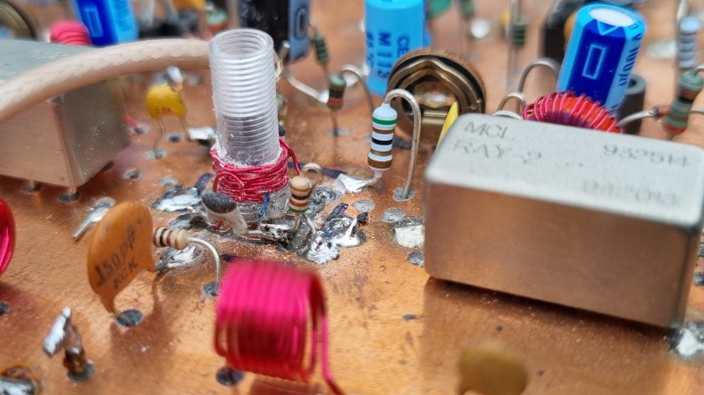
MY TESTS
I
built up a number of circuits using various suggested audio devices.
connected to a sbl-1 H.C. mixer fed by a signal generator (hp8920a) using +7 dBm at 29.6 MHz and the rf port fed by a variable output RF
signal generator at 29.6 Mhz (Agilent N9310a). Both NOT
particularly low phase noise sources, I used a high gain audio
amplifier with a speaker to hear the audio response of the low noise circuits to the various
levels of rf at 29 Mhz from 0.2 uV upwards . I could audibly hear
the results of the different amplifiers but it was hard to put an accurate
number to the performance . To
achieve a quantitative response, I measured s/n using a sinad meter .
I used the 1Khz audio offset heard on the receiver speaker to
activate a signal to noise meter, thus displaying s/n and I assessed the
rf sensitivity to achieve 12dB s/n. .A lot of those "discovered"
semiconductors are now almost unobtainium so be careful what you buy from ebay
and aliexpress they may not be what the label says they are !
The best so far using a
2n3044 /2n3041 (d.c switching transistor! from Mouser electronics ) combination was 0.4 uV
for 12dB @ 29.6 MHz using no rf amplifier . All circuits were done
on double sided PC board for best audio and interference screening. until I
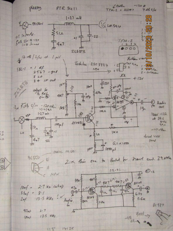
discovered ZTX851/951 devices .Just
the other day I received some ztx851 and ztx951 transistors also
some LSK170 low noise jfets , these are supposedly particularly low audio
noise transistors .
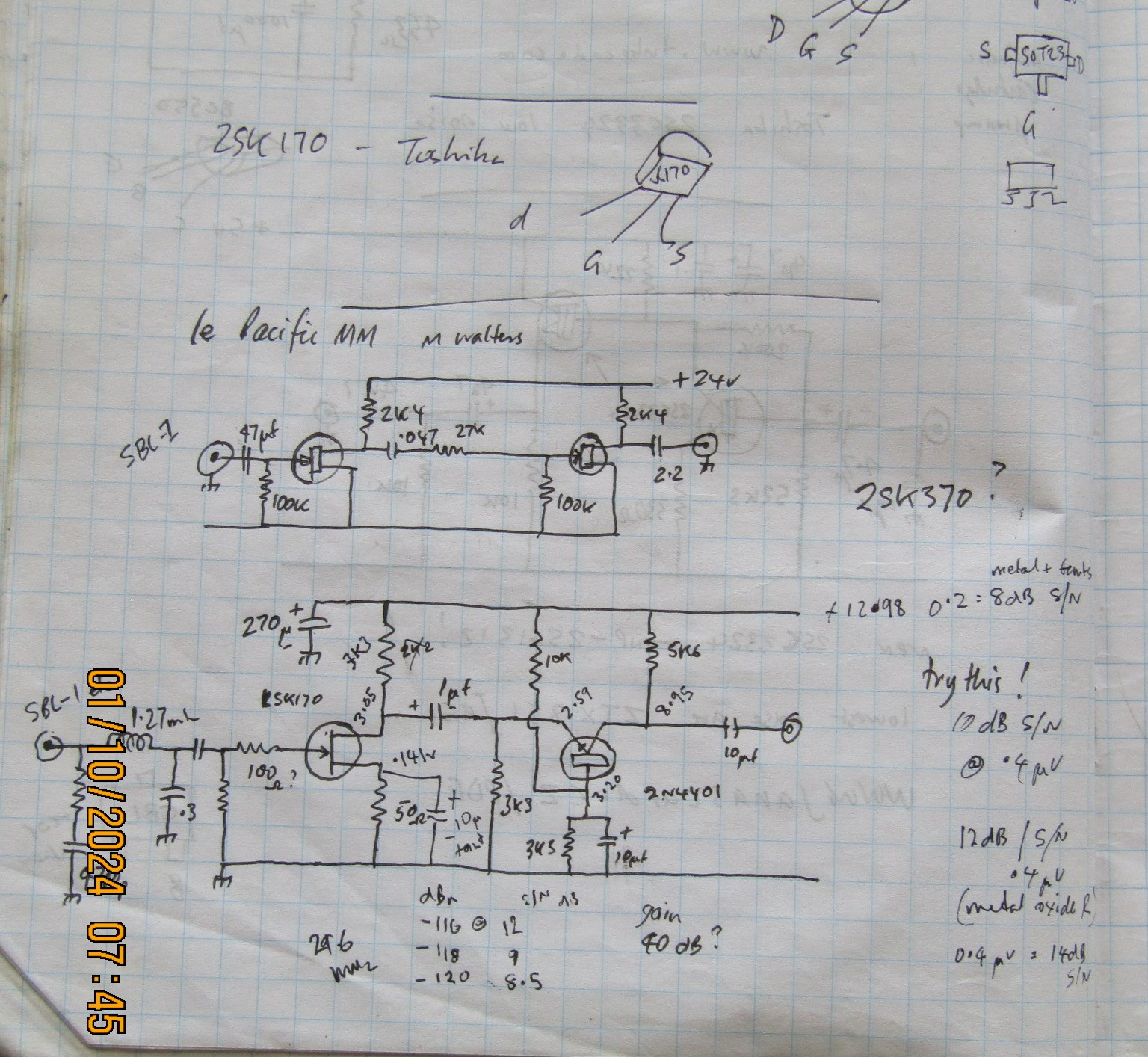
For the jfet , I did try a “LE
PACIFIC MM” preamp by M Walters followed by
my addition of a low noise grounded base 2n4403
stage . the best I could do was 14dB S/N at 0.4 uV at 29.6 Mhz . Its
certainly a less "complicated" than the Richard lee circuit and may
be ok for what you require in your project ??
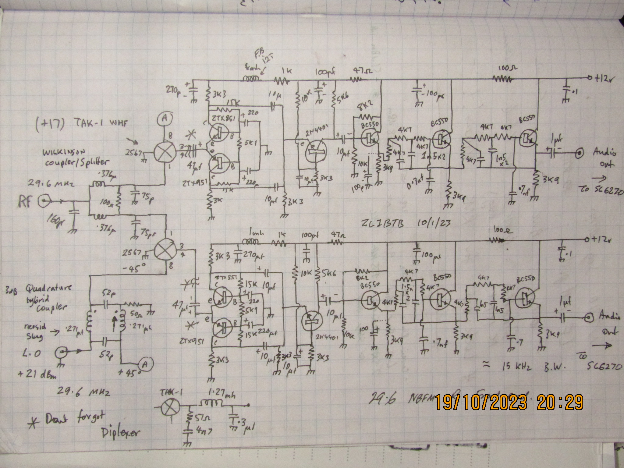
However
the “Richard Lee” based preamp circuit with the ztx851
and 951 achieved 12dB S/N at 0.3 uV at 29.6 Mhz . Not to shabby when
compared to other 10meter receivers !I somehow dont think Im going to better this
performance ( which is very good for a direct conversion front end
with NO RF preamp !!) I shall settle for this “Richard Lee”
configuration for the “i” and “q” sections
of the receiver The
Modified “Richard lee ..circuit first appeared in “wireless
world” magazine in July 1981 and is still a record beating
circuit (no pun intended). “Marshal Leach” has a good
article of a modification of this preamp circuit as well , if you
web search the originals youll see Ive put an extra low noise 2n4403
NPN grounded base stage on the tail of the preamp to achieve about
a total 35 dB of audio gain. This will be plenty to set the overall
sensitivity of the receiver
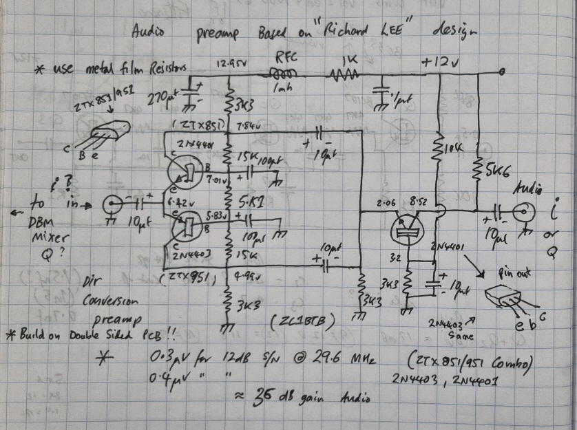
Front end preamp 35 dB gain ,
very low noise
best low noise audio preamp I have ever come across so far and boy does it perform !!
Note:
This is the low impedance common base configuration in push
pull configuration and there are no noise generating resistors at
the input ( unlike a lot of other low noise preamp circuits ), high
value resistors generate nanovolts of noise at room temperature and
the higher the resistance, the more the noise they make ! Use only
metal film resistors in your low noise preamps and avoid carbon
film resistors they are noisier than metal film.
You have to use very low noise D.C for direct conversion receivers .forget switch mode amplifiers
too much ripple .use well filtered linear power supplies ,
you dont want audio noise on your D.C lines destroying your S/N of the received
signal. Many Audiophiles seem to push the applications of battery
based power supplies in their low noise preamps and they change the batteries
when required .
The
other advantage of these bipolar configurations is they are low
impedance ( for M.M pickup 30 ohms or much less so the match to a
50 ohm dbm is not to bad compared to the low noise high Z jfet amplifier
configurations ).
Passive hot carrier mixer optimal performance
is very dependant of port match , be mindful of this. try to match ALL
ports if possible see
https://www.minicircuits.com/app/AN00-011.pdf
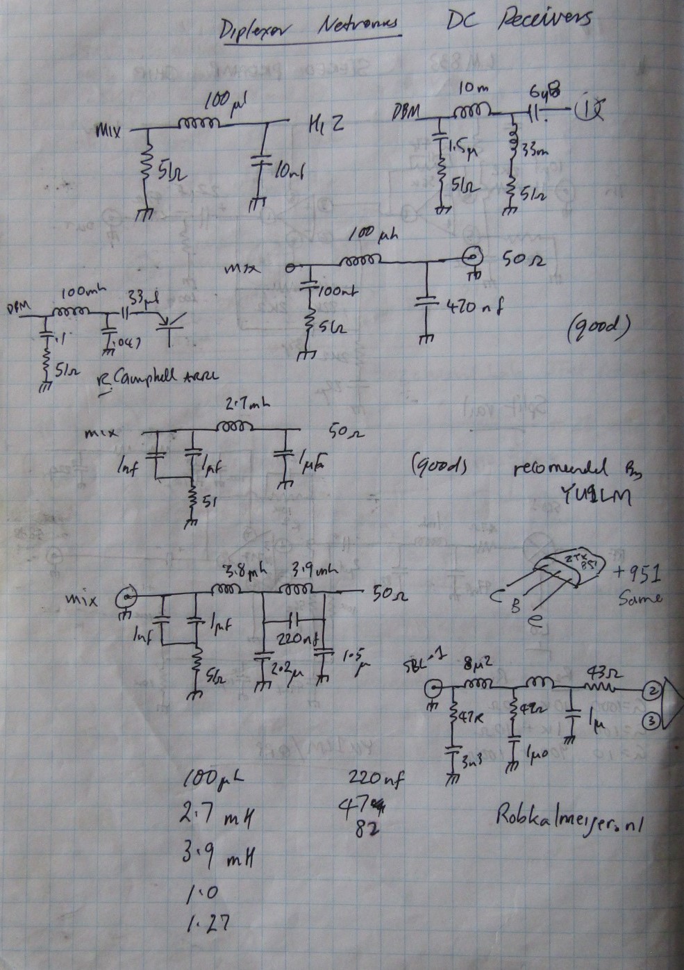
The experimental front end circuitry to get from RF to audio is just a simple minicircuits TFM-2 a +7 dBm hot carrier mixer, no tuned circuits , just a simple I.F output diplexed to terminate the mixer if port in 50 ohms and this lets only the detected audio past into the preamp and thence to a simple audio mp driving a speaker .
In the receiver proper I will use a pair of + 23dBm minicircuits TAK-2 Dbmixers, one for “i” and ! For “q” channel . The other aspect to good low noise performance in a direct conversion receiver is to have as lower phase noise from the Mixer conversion oscillator, A noisy local oscillator will impress its phase noise on top of the wanted signal resulting in a degradation of the S/N, so choose you oscillator carefully , Well designed crystal oscillators can exhibits very low phase noise, I will use crystal as I want to be on a fixed frequency . I don't think the HP8920 phase noise of its signal generator is all that crash hot !(110db/Hz) and the N9310a is worse at 95db/Hz
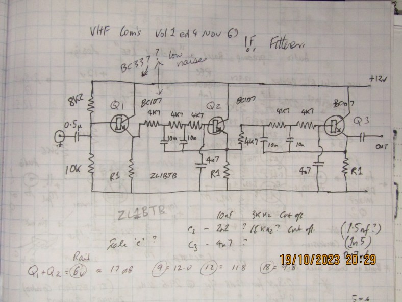
DJ4BG Audio Sallen and Key filter
The
noise figure of a radio receiver is directly related to the bandwidth of the
receiver, so providing just enough receiver bandwidth to operate the
mode required will go toward improving receiver performance ,As
is typical of radio receiver design the mixer stage is followed by
filtering but in this case at audio frequencies. I have used a very
good “Sallen and Key” design stolen from VHF Comms
magazine “Active Audio filters” by DJ4BG , Vol 1 Ed 2 May
69 pg 110 and Vol 1 Ed 4 nov 69 pg 218. These are very good and simple
to build and perform very well . The Bandwith here is 15 Khz which should
be good for 5Khz Deviation nbfm . Its a little bit of an over kill
but I used low noise BC550 transistors in the filter modules , Im
a fan of not adding noise to the circuits even though the sensitivity
of the receiver is set by the front end, high levels of audio hiss
added by subsequent stages can be tiresome to listen to.
Even
though its an FM receiver I have added some Audio AGC to the design
in the form of a plessey style VOGAD I.C the SL6270, in each chanel
, this has about 50Db of range to hold the levels somwhat constant ,
I could have used several other chips like the MC1340 which has up
to 80dB of control but requires outboard circuitry to achieve the
control voltage ,hopefully Ill get away with 50 dB !
The other Thing to watch for is to keep the gain and and phase shift
the same in both i and q channels , the performance of these
D.C receivers depends on cancelling of frequencies at various stages
so we dont want large discrepancies in amplitude and phase between channels or
things are not going to cancel completely
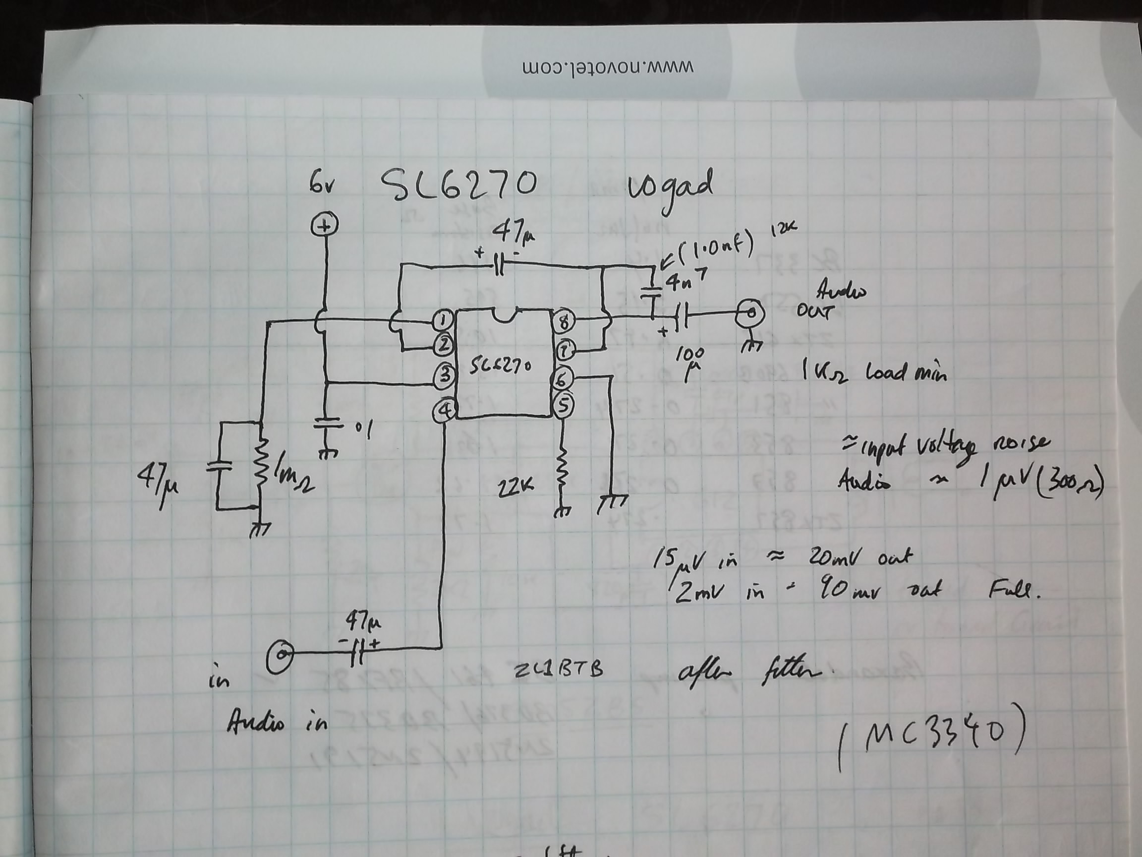
Plessey style VOGAD I.C, the SL6270, in each
channel for audio AGC
With the “Barber .Wever” design, the amplified and filtered audio “i” and “q” channels are subsequently mixed up to your wanted demodulator frequency by another set of mixers ,in this case two 455Khz, mixers fed by a common 455 Khz Osc with two quadrature split 90 deg outputs at 455 Khz. The two derived 455KHz signals are summed together and cancel the unwanted sideband while adding the wanted sideband ,this summated 455 KHz signal is connected to an FM demodulator circuit.
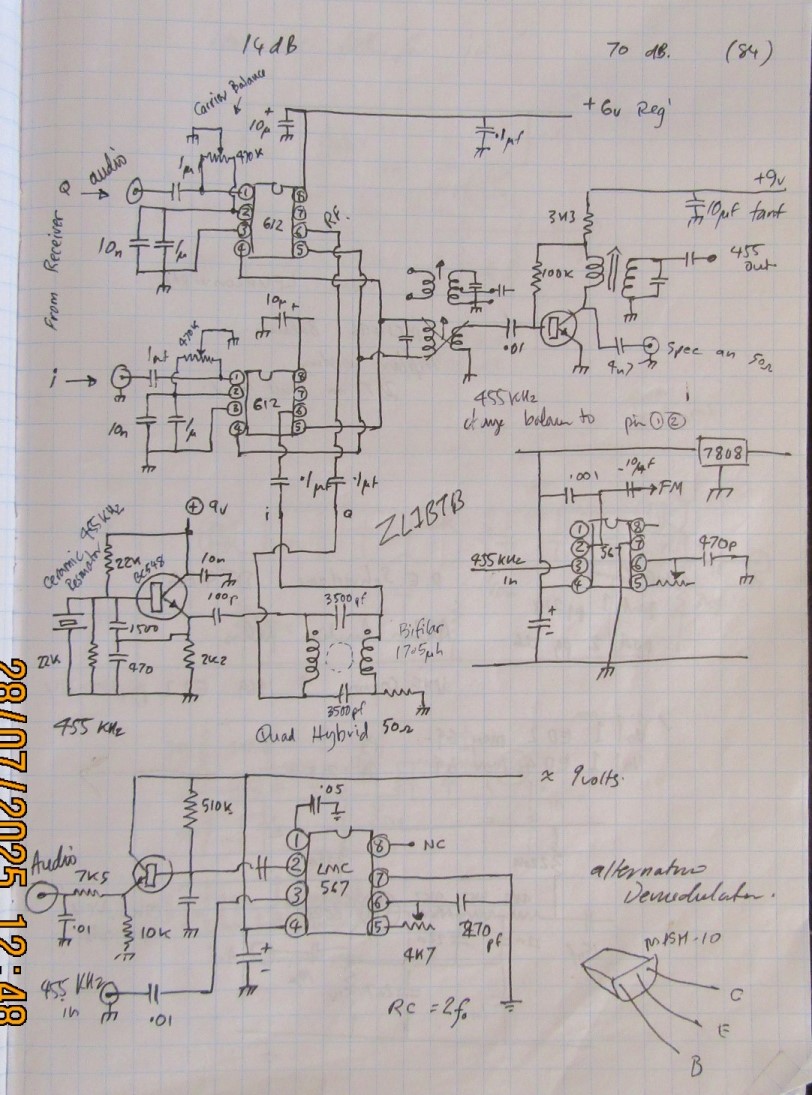
Tail end of the "Barber Weaver" receiver where i and q get transformed back to a frequency that you can o something with !!
I
decided to use two NE612 active Dbm units as they
can have additional L.O carrier balance added to reduce L.O output
and are simple to use . The MC1496 of gibert configuration series is a much better
double balanced mixer with
60 db of carrier suppression at 500 Khz ! but they are complicated with 14 pins
and so many extra surrounding components , however their 60 db of L.O
(455Khz)carrier elimination would be a strong point to minimise 455 KHz carrier
leak through to the FM demodulator
We
will see how the NE612 performs , Dont forget to put the carrier
balance circuitry on the quadrature 455Khz input ports , as its the
frequency you want to suppress the most , you dont want the 455KHz
quadrature Local osc getting into the fm detector , only the
upconverted audio wanted signal !( this is where the MC1496 will
excel) I did infact try the rf2317 modem i.c it has its own quadrature
oscillator circuitry ,but requires a 910Khz osc for 455 Khz I.F but i was
a little disappointed in its performance . the poor internal carrier
balance allowed to much unmodulated 455 through to the fm demodulator causing it
to "quiet"
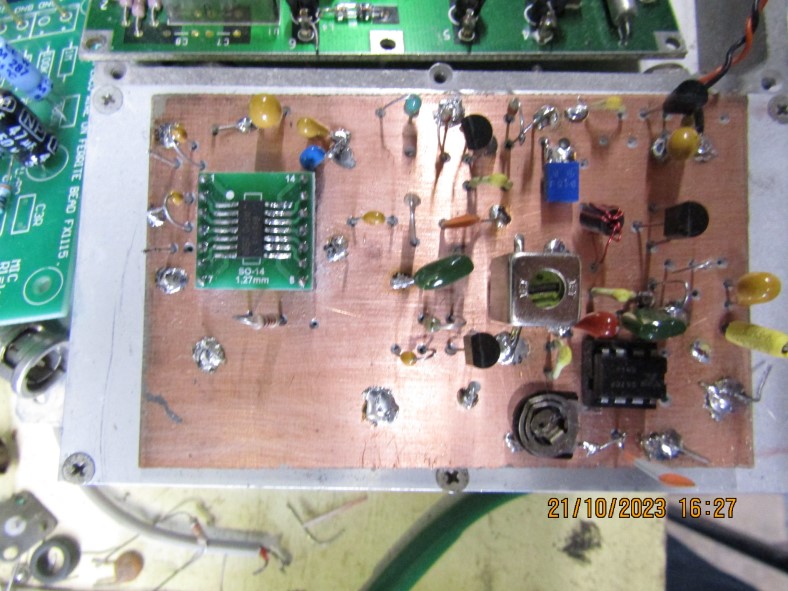
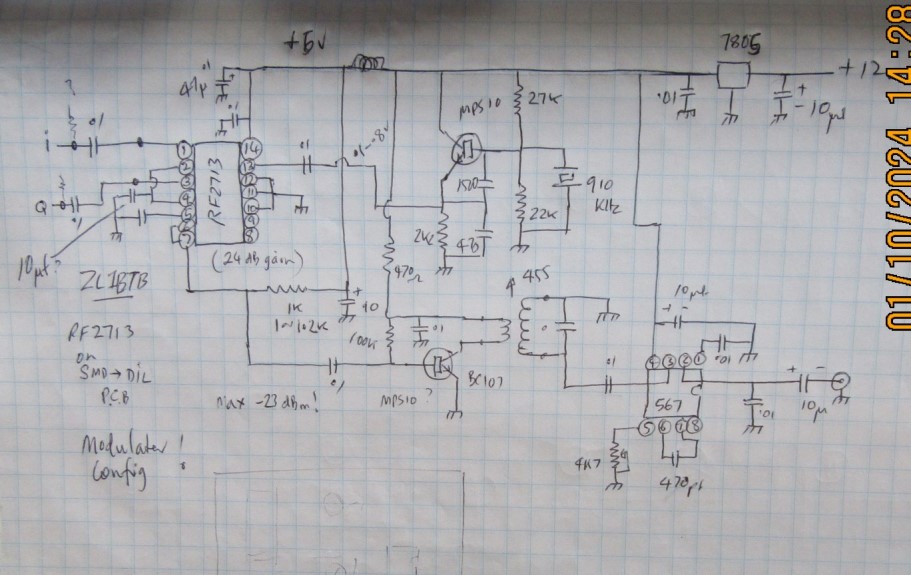
RF2713 mod/demod board and NBFM Demod
For my FM demodulation I will use an amplified NE567 tone decoder ,as Its an easy circuit to build and it works well at 455 Khz , requires only -35 dbm to work and outputted around 60mv of audio (5Khz deviation ). I wonder if I should use the LM568 as it has been also optimised for fm use in domestic 110v wired intercoms ,it is obsolete now but I have some smd versions somewhere .. The NE567 FM module will have one stage of R.F amplifcation with a single BC547 transistor. Notice the configuration of the 455KHz interstage transformer , the transistor collector connects the low impedance side and the tuned circuit side connects to the 25 k input impedance of the “567 .I have discovered this configuration works much better than the transformer connected the other way around !!
The mute circuit will be a standard FM noise mute configuration where the fall in received noise will open the receiver . The NE567 can be pushed to provide this feature as well but the 455Khz input signal needs to be almost noise limited for this feature to be exploited well.
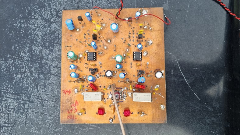
Experimental front end using i and q front end and "dick" AD797 low noise amp circuit
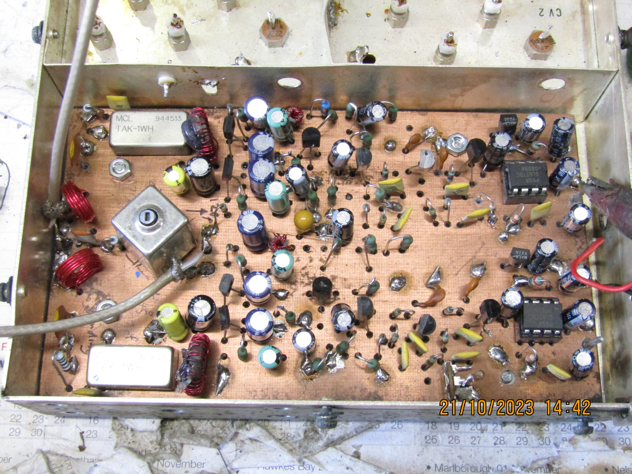
The
completed experimental 29.6 MHz NBFM receiver with i and q
output (less demodulator)
Schematic of above above receiver
more to follow