Common rail diesel Interference suppression
When it was time to get a larger vehicle because the family was growing in size physically and socially ( they now drag their friends along ) I thought it was time to trade in my little Diahatsu Feroza Four wheel drive ( petrol engine fully suppressed by me for HF . ) which stood me well for 11 years , and get a much larger vehicle . I needed something to tow the family fizz boat , be able to visit amateur radio club repeater sites on farm hill tops and have plenty of seats with seatbelts for all occupants. so I opted for the new Isuzu ( GM ) "Bighorn" or "trooper" if your Australian , It is a large vehicle with plenty of room , heaps of grunt , and available in Diesel , I have always wanted a diesel .Thought it would be great for Ham radio . NO Sparkplugs!! therefore no ignition interference! how wrong i was . The new 3.0L double overhead cam Turbocharged diesel engine is a computer controlled common rail diesel, 40% more powerful than the old 3.1 L donkey of earlier model Isuzus and really thrifty on fuel and with much lower exhaust emissions BUT you should hear the noise on HF !!! give me back my old Feroza! I should have known anything with a CPU was going to generate noise and i didn't expect to hear the "click click click "of ignition coming out the speaker of the icom 706! no way could the noise blanker quash that ! so i had to get tough .
The common rail diesel does not have the standard mechanically driven injector pump . In the Isuzu 4Jx type engine , there are injectors feed from a high pressure fuel line but they are hydraulically actuated but electronically controlled . Imagine the injector as a medical hypodermic syringe full of diesel fuel that sticks into the cylinder . the plunger of the syringe is forced down under great pressure by a small hydraulic ram which is feed from a separate very high pressure engine oil pump . The valve to open and close the high pressure oil is controlled by an electric solenoid ( read amps , fast rise and fall square waves ) by the engine management control CPU and timed to coincide with compression ignition around top dead centre of the piston travel . This electronically controlled system works very well and does a marvellous job in making the engine run well , gives fine control and great fuel economy . BUT the HF noise is horrendous.
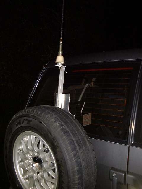
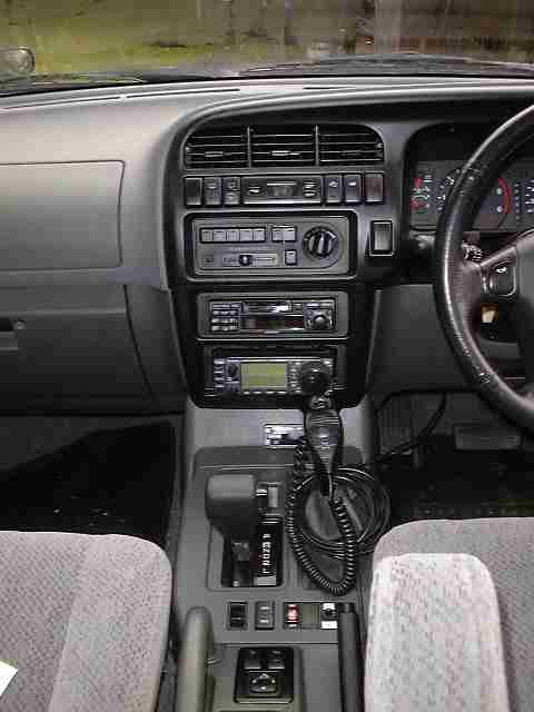
I mounted my HF helical antenna on the back of the vehicle by way of a flat plate bracket that mounted over the 3 holes that holds the spare wheel onto the rear door , the antenna base is at roof height and can hinge forward flat onto the roof ,if I want to go into a car park building, Make sure you have a good bonded earth for the HF radio in the car . I mounted my whole Icom 706 MkIIG in the consol of the vehicle . and ran the power cables with a ferrite suppression bead , straight to the battery ( later on I mounted the SGS239 Auto antenna tuner in under the spare wheel at the back of the vehicle .. )
I had a 20 over 9 noise level, totally HF unworkable, so I started to tackle the problem . OK lets see where it is coming from ie what is radiating the signal . These days motor vehicles are built in an effort to be audibly quiet and comfortable ,so a lot of components are rubber mounted. No low impedance electrical contact there !! DC continuity is usually provided by earth return wiring that may be ok for 12v DC flow but will be a high RF impedance ,no way is it going to bypass Rf noise. I went and did the standard metal to metal electrical bonding using my favorite material , copper braid stripped out of RG6 half inch coax. I bonded the bonnet to the body at the hinges and where the bonnet closes at the front
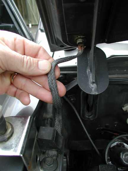
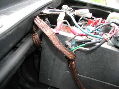
bonnet bond battery bond earth front lower contact point bonnet
upper contact point bonnet ( self cleaning!!)
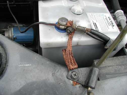
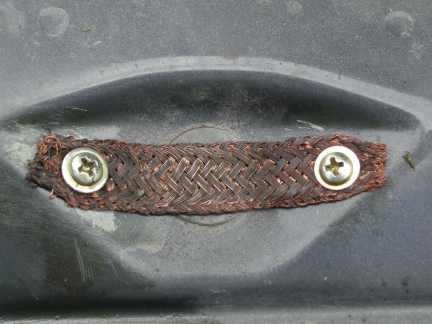
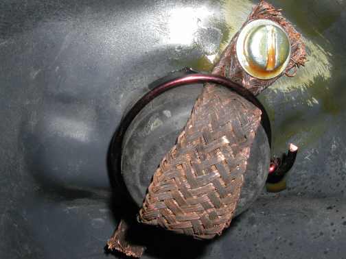
see photos.. and don't forget the sand off the paint to get good electrical contact , .When you have tightened up all the bonding screws give the area a good coat of waterproof wax like spray grease to inhibit rust. ( CRC soft seal) I ran an extra bonding braid from the battery earth straight to the body . I them bonded the exhaust pipe to the chassis rail midway down the underneath and at the tailpipe end using copper braid and a large stainless hose clip
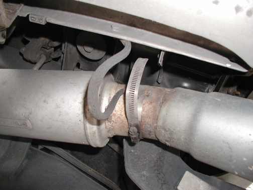
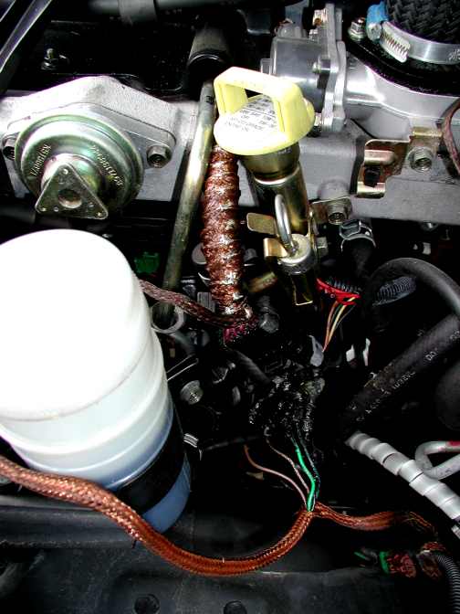
stainless hose clip on exhaust , engine to firewall bonding
this is always a problem spot as exhausts get hot and there will be corrosion of bare metal after a while, you can protect the area with a spray of VHT high temperature spray paint . The bodywork of modern motor vehicles is mounted on rubber !! don't forget to climb underneath and earth the body work to the chassis at each "corner" of the vehicle this was a prick of a job on this wagon as you needed to undo nuts set up long threaded bolts to get the braid in the correct position . While there you could bond the transmission to the chassis rail .
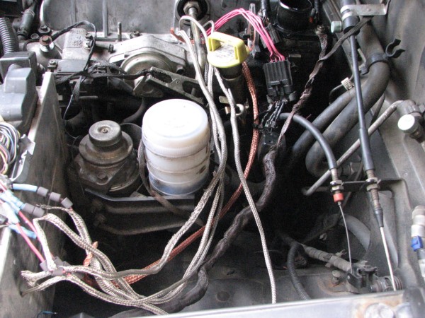
At this stage the HF noise was starting to come down to a respectable S9 !!! ha ha . not good enough yet buddy !! want to be able to work 10m AM !! so it was into the engine compartment and concentrate around the ECU box. This is a large flat aluminium box with a HUGH bunch of cables coming out of it !!
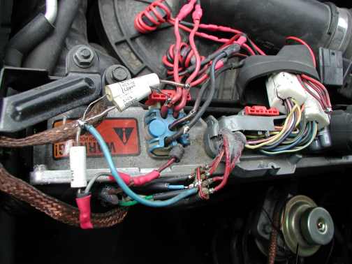
ECU unit with bonding straps and bypassing earth strap from rubber mounted ECU to body
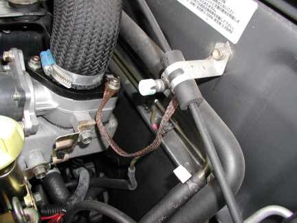
Out with the Fluke scopemeter ! I measured very fast rising 60 V spikes going positive and negative on the injector control cables (so they have active opening and closing !!) I wound flat copper braid around the injector control cables soldered it together and earthed it at each end .. made a small improvement .
note: Initial braid cover on solenoid control wires Ferrite toroids on positive and negative to ECU
I also clamped ferrite suppression beads onto the multi cables that go to the ECU. Now I did make a small low pass filter of ferrite beads and feed through caps and put them in series with the injector control lines , (i did try bypassing the solenoid control wires with 0.1 uF 300v caps but the upsets the fuel injection timing and the engine does not like it when idling ). this produced an additional benefit. The biggest effect I found was by passing the 5 solonoid control cables ( one is the common earth return ) as a complete 360 degree loop thru a large clamp on ferrite bead . and in finding this on hindsight ,i would try this as my first attempt in ECU suppression. we are now down to a very acceptable level of ignition interference .
To get lower in interference level , you have to fiddle with the position of bonding straps around the motor and ECU but i think the worthwhile effort become exponential with respect to the achieved results. There was places midway along the ECU bonding strap where if you touched it to the fuel primer metal the noise would drop even more / You will find that there are low level carriers at different frequencies across the HF band , emanating from the ECU , some even have a real digital "note" to them
I hope this has been of some use to someone when i get some spare time I may have another concerted effort to improve things even more .
MK2 Mods Nov 2011 success
!!!
I was still determined . I had time and inclination to improve the current situation , I suspected that if I completely
screen the injector leads from the ECU up to the rocker box cover .
this surely must improve the situation , The last time I did this was on
my 1979 Honda Accord and in those days I was able to work the oscar
series of satellites 2m up and 10m down mobile with no vehicle noise what so ever
on ssb .
I had at my disposal an injector wiring harness from the 4JX-1 Isuzu common rail
Diesel ,this was a good find as I was reluctant to pull the rocker box cover off
to expose the twin camshafts and the injector solenoids,to see what was
inside .... I peeled the black cable wrap of the pink
injector wires to leave them bare,
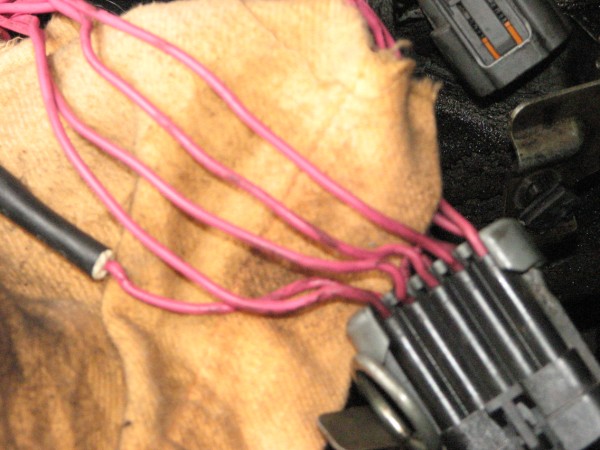
earth return and 4 injector solonoid control lines
Using the notation on the loom connector grey /black plug ( there is letters
stamped on the side) I isolated cable A, the common return for
all injectors , G,H,J,K ( there is no " i"
just like in the word Team!) are the individual injector
cables , I traced the wires from the loom injector thru the
large grey/black plug to the ECU Unit , I then one by one pulled out
each corresponding pin out of the grey/black plug ( poke a long thin
rod down the inside of the square hole in the pin and you will unclip the
pin from inside the plug and the wire will pull out ) but before
you do you will have to take off ( unclip) the grey cable holder off the
top . Mark the cables permanently A, G H J K ,
So you dont get lost , start with one cable , lengthen it , slip on the braid
and connect it completely before doing the next injector cable then you wont
make a connection mistake
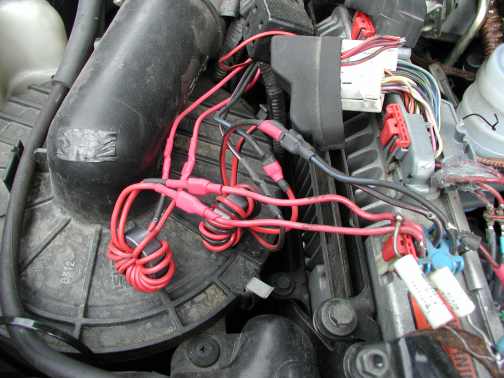
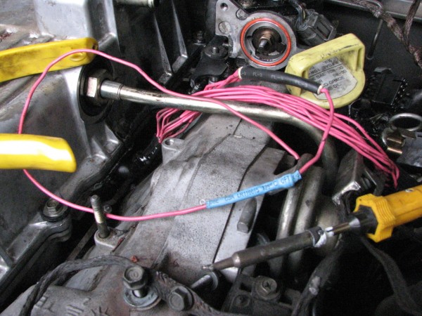
I soldered the extension cables on, so I could go directly from the cylinder head to ECU, the soldered joints had two layers of heat-shrink, and then I fed the cables thru the correct length of RG58 Braid from old coaxial cable ( as measured against the modified lead ) feed you wire in through the side of the braid about 30mm up from the end and do the same at the other end this will give you 30 mm tassels of coax braid to connect to at each end and not interfere with the wire in the centre . The rest of the grey black plug carries 5 other sensor cables ,they where left as they where found .. . The 5 braid tassels at the cylinder head end were collected together and soldered to a large connector and bolted to a convenient unused spare thread on the intake manifold , That is the injector end earthed.
I have now used old RG6 braid to cover wires
.jpg)
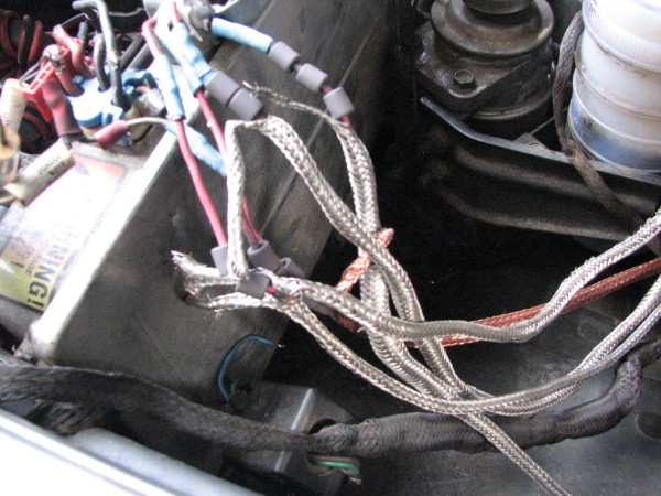
I did exactly the same at the ECU end , gathered the
coax tassels together and crimped them into a bolted type connector
,soldered it then drilled a small 3mm hole in the outer rim of
the ECU ( where it can do no damage ) and bolted the tassel connector the the
ECU case . I slipped about 3 large Ferrite beads over each of
the wires where they connected to the ECU hoping these will help absorb
some RFI but I dont think they do a lot to be honest , ( ended up
removing them when I soldered the toroids on ) A mobile run
showed a huge improvement in "injector Noise" on the IC706 radio .
I found that when I stopped on the side of the road in a very quiet RF
location and opened the bonnet ,and while listening to the radio on HF
ie 18 Mhz "touching" (finger capacitance)
I replaced the large ferrite beads with computer board
Toroids
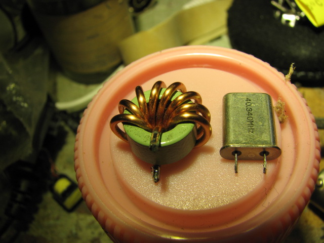
computer motherboard torroid compared to hc49/u xtal
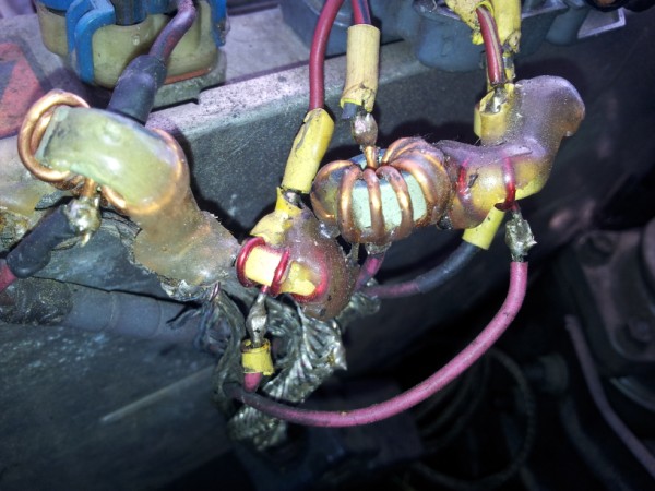
This the five cables at the ECU end with series torroids
the injector return cable induced more noise than "touching"
the injector cables going into the ECU . So I came back home and placed a
small switch-mode power supply toroid with heavy wire ( I obtained from an old
computer motherboard ) , in series with the "common" wire going into the
ECU . That dropped the noise even more , so I used
more of these and put one in each braid shielded lead at the ECU end ,
that were feeding each injector solenoid ,
to see if I can eliminate all injector noise completely ! I
glued the computer torroids together with hot glue to vibration
wouldnt break the solder joints ... Well now the "ignition " noise on the HF bands on ssb is down to scarcely
audible stage where quiet atmospheric noise is easily heard , even in AM
mode the HF noise is low enough never to be a problem . I have
absolutely no audible engine "ignition" noise above 24 Mhz , not a peep on AM
mode. even at 2m !
Its taken me a while but it has now been worth it .................73 de Mike ZL1BTB