Coaxial Resonators:
by MIKE PINFOLD, ZL1BTB
(Images taken from Agilent E4403 spectrum analyser supplied by http://www.rftest.co.nz/ )
Cavity filters, or more correctly coaxial resonators, are the cornerstone of good repeater performance. However, there appears to be some sort of black magic in the way they work or how they achieve their performance.
A coaxial resonator is much like a quarter wave stub, but open-ended. It can also be likened to a quarter wave antenna enclosed within a conducting chamber and a resonant L/C tuned circuit, encompassing many of the features of each.
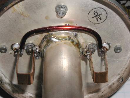
In most coaxial resonators the "antenna" is excited by a magnetic coupling loop at the resonant frequency and energy is removed by another loop placed next to the base of the center resonator. The center resonator is surrounded by air and there is in fact an optimum ratio of inner case diameter to outer diameter of the resonator of 3.25, which works out to give a characteristic impedance of around 70 ohms
Factors affecting coaxial resonator performance
1 - Diameter of center resonators
This is chosen to achieve an inner resonator to outer casing diameter of 3.25, arriving at the optimum 70 ohm impedance. This gives the highest available Q.
2. Length of resonator
This determines the operating frequency of the formed tuned circuit. Length is inversely proportional to frequency, much like any antenna.
3. Coupling loops
These are the means by which energy is input or extracted from the
tuned circuit. Loop size determines the amount of coupling. Two major factors have a
pronounced effect on coupling: (a) the length of the coupling loop wire adjacent to the
center resonator. The longer this is the more of the energy field around the resonator is
intercepted hence a greater influence this has on the coaxial resonator's performance. The
longer this wire or loop is next to the center resonator the higher impedance the input
loop becomes; and
 TIGHT COUPLING, LESS LOSS BUT WIDER 3dB POINTS
(b) the spacing of the coupling loop to the center resonator-ie, the
closer the above mentioned loop, the more stronger field it intercepts around the center
resonator, the greater influence it has on tuned circuit performance. The reverse is also
true with respect to loop-to-resonator spacing.
It is the manipulation of these two factors, that plays a major part in
obtaining desired performance of coaxial resonators and generates the biggest headache and
level of frustration. For it is with these factors that filter loss, bandwidth and notch
depth are juggled. LOOSE COUPLING AND THUS NARROWER 3dB BANDWIDTH
Materials of construction
Most commercial coaxial resonators are constructed of copper but there is an increasing use of aluminium as a casing material. The actual resonator itself, and quite often the inside of the casing, will be silver-plated to increase electrical conductivity, reducing "skin loss" and hence assisting in the maintenance of high Q.
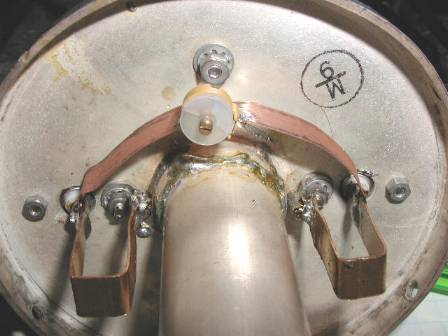
The coupling loops are of silver-plated copper and the center resonator
may even be gold-plated at the far end, in the region of high RF impedance.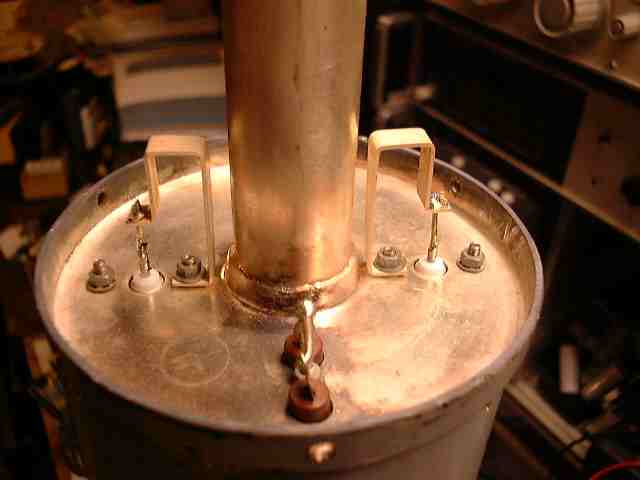
The center resonator is usually silver-soldered to the top-cap and the far end of the casing closed off with a copper end-cap. The top-cap and end-cap are usually secured to the casing by machine screws or even soldered once all adjustments have been made.
5. Frequency of operation
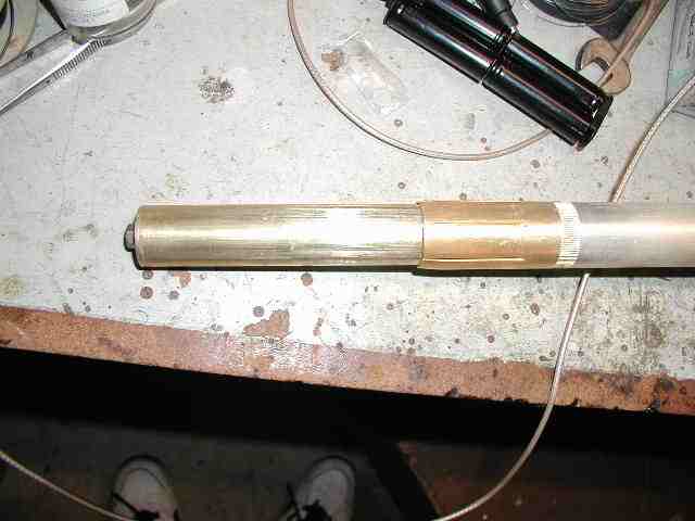
This is governed by the electrical length of the center resonator and is usually very close to a quarter wavelength at the frequency of interest. This central portion has within it a screw mechanism by which a telescoping metal tube at the free end of the coaxial resonator is able to effect its mechanical and electrical length, and hence its operating frequency. Most high electrically conductive metals have large coefficients of thermal expansion hence it is possible for the length of the center resonator to change with extremes of temperature and more importantly change its resonant frequency. To combat this effect commercial designs incorporate a threaded rod of invar, an alloy with an extremely low expansion coefficient which holds the length change to a minimum over extremes of temperature.
Modifications and performance
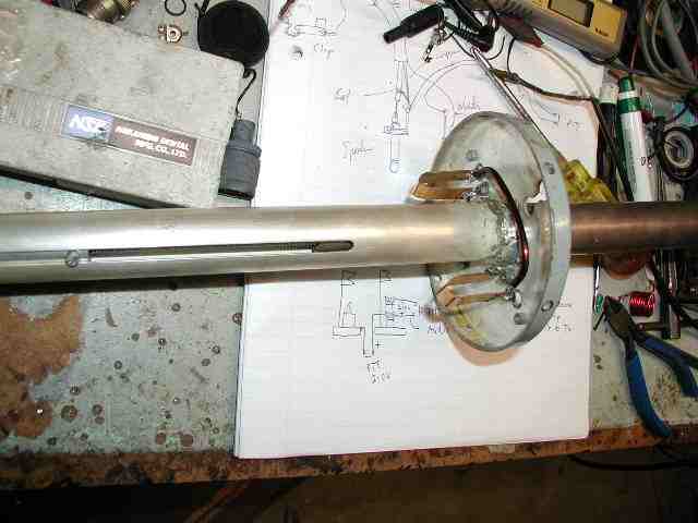
The set of coaxial resonators used in this article were ex-government (now of course corporatized), made by TCA of Australia, 100MHz versions type 1564/101/1NZ.
They had been cut down in length externally and internally to bring the operating frequency up to 146 MHz band. The outer casing had a finished length of 610 mm, the center resonator length ended at 510 mm at 144.350 MHz, but allowed some adjustment length for other frequencies. The resonator itself and its screw thread mechanism were somewhat difficult mechanically to modify. The resonator was removed from the top-cap to achieve this.
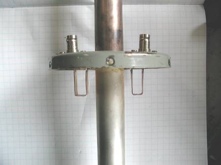
The original coupling loops of 100 MHz coaxial resonator are designed for 50 ~ in and out, hence to use them for 146 MHz scale their dimensions by 100/146 in overall length parallel to the resonator. The coupling loops were re-connected to the BNC sockets and top-cap. The spacing between the pick-up loop and center resonator controls the degree of coupling energy into and out of the tuned circuit at its resonant frequency.
Experimental section
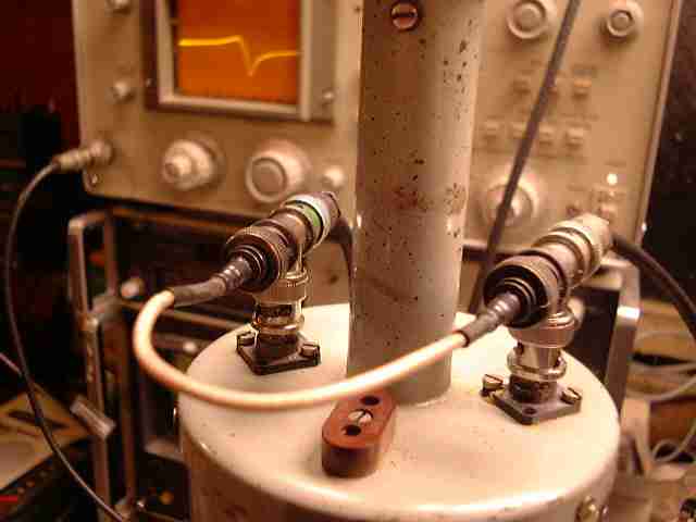
With the aid of a spectrum analyzer with a built in tracking generator, the characteristics of coaxial resonators on the 2 m band can be examined. The frequencies of interest were the linear repeater input and output frequencies for which these resonators were modified. In the test set up the 50 ohm generator feeds the coaxial resonator input and output feeding the spectrum analyzer.
1. Band pass performance
Sweeping the signal over 5 MHz produces the response of Figure 1. see SIMPLE TUNED CIRCUIT RESPONSE Above The 3 dB points are about 573 kHz and insertion loss under 2.5 dB. When you look at the response of this tuned circuit you see the attenuation is very poor 600kHz away from center frequency. Clearly this set up would be very inadequate for repeater filtering purposes to keep the transmitter out of the receiver.
The anti-resonant notch
There is a simple modification to this band pass configuration that
will produce the required frequency response. A notch at the unwanted frequency of the
transmitter to keep it out of the receiver is obtained by placing a small value capacitor
(2-20 pF variable trimmer) across the input and output loops (Figure 2). This produces an
amazing effect. Figure 3 shows a notch in the swept response below the pass-band peak. The
notch depth depends on the Q of the tuned circuit.  CAPACITOR ACCROSS COUPLING LOOPS, GIVES LOW SIDE NOTCH .
Compare this to the simple band pass response. On first examination the capacitor looks
like a short-circuit across the loops, but the overall summation of phase shift across the
capacitor and phase shift across the tuned circuit, both frequency dependant, produces
this curious but very useful effect.
CAPACITOR ACCROSS COUPLING LOOPS, GIVES LOW SIDE NOTCH .
Compare this to the simple band pass response. On first examination the capacitor looks
like a short-circuit across the loops, but the overall summation of phase shift across the
capacitor and phase shift across the tuned circuit, both frequency dependant, produces
this curious but very useful effect.
Fig 3
The amount of capacitance controls the peak-to-notch frequency
difference; more capacitance-brings the notch and peak closer together while less spreads
them further apart. PHASING CAPACITOR AT MINIMUM C
How close one can get them depends entirely on the overall Q of the system.) Circuit Q
depends directly on the amount of coupling hence, in an over coupled resonator with its
inherent very low insertion-loss, it will be very difficult to achieve a close
peak-to-notch with good rejection 'notch depth.
PHASING CAPACITOR AT MINIMUM C
How close one can get them depends entirely on the overall Q of the system.) Circuit Q
depends directly on the amount of coupling hence, in an over coupled resonator with its
inherent very low insertion-loss, it will be very difficult to achieve a close
peak-to-notch with good rejection 'notch depth.
 INDUCTOR ACCROSS COUPLING LOOPS HIGH SIDE NOTCH
The same phenomena occurs with a "shorting conductor" or a
"shorting coax"-(Figures 4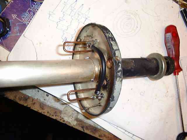
and 5). However, the pass band peak and rejection notch are reversed infrequency position
. The peak to notch separation is once again controlledby the amount of inductance; the more inductance the wider the separation between notch and peak, while less inductance allows them closer together. Once again the depth of the rejection notch and separation are controlled by the circuit Q.This effect can be obtained by using a piece of 50 ohm coax between the input and output Its length governs the peak to notch separation in the same way as does the shorting inductor.
There is a curious but useful effect of the capacitor across the two BNC inputs. You can tune for notch on the high side OR the low side of the pass-band. By altering the value of the capacitance you essentially control/cancel the amount of inductive reactance presented by the inductance of the leads that connect the capacitor to the BNC connectors
3. Suckout Notch
This is the opposite of the band pass response and the coaxial resonator is placed in the feed line as is shown. At the frequency of resonance the tuned circuit begins to accept energy from the coax feed reducing the amount of power reaching the spectrum analyzer, hence the dip in the swept response. However, as you can see, the overall depth of the notch is only 18 dB. This depth is governed by the amount of coupling; the greater the coupling the deeper and broader the notch becomes, the less the coupling the shallower and the narrower it becomes
 LOOSE COUPLING
 TIGHT COUPLING
 USING PHASING CAPACITOR TO CANCEL (almost) THE LEAD INDUCTANCE.
Coaxial resonators designed with the same input and output impedance
can be coupled together to perform various band pass configurations. Placing them in
series will add losses and add notch depth if they are on identical frequencies.  TWO FILTERS IN SERIES PROVIDES ADDITIVE PERFORMANCE
Placing several coaxial resonators in series with pass bands and rejection notches in the
correct places one can get enough isolation between a transmitter and receiver to run them
both off the one antenna. This is called duplexing and the group of connected coaxial
resonators called a duplexer. Transmitter to receiver isolation figures are measured in
decibels and one usually requires at least 80 dB to achieve duplexing.
TWO FILTERS IN SERIES PROVIDES ADDITIVE PERFORMANCE
Placing several coaxial resonators in series with pass bands and rejection notches in the
correct places one can get enough isolation between a transmitter and receiver to run them
both off the one antenna. This is called duplexing and the group of connected coaxial
resonators called a duplexer. Transmitter to receiver isolation figures are measured in
decibels and one usually requires at least 80 dB to achieve duplexing.
In a repeater set up, (eg, transmitting on 144.350MHz and a receiver on 144.950MHz) the connection of coaxial resonators would be as follows: for receive coaxial resonators are tuned to pass 144.950MHz and have "capacitive shorts" between input and output connectors to place a rejection notch at the transmitter frequency of 144.350MHz. This keeps the transmitter from overloading the receiver and requires several resonators connected in series to achieve this.
On the transmit side the coaxial resonators are required to pass
144.350 MHz: and reject 144.950 MHz. It may seem silly rejecting the repeater input
frequency from the transmitter but a transistor or even (dare I say) valve transmitter has
a broad noise pedestal centered symmetrically around the carrier and, at 600 kHz away from
the carrier, the noise level generated by the transmitter may still be in the milli-volt
level. The rejection notch at the receive frequency attempts to keep noise off the input
frequency and let the receiver respond to the wanted micro-volt signals that would
normally be buried in the transmitter noise. A novel feature of coaxial resonators is the
phenomenon of harmonic resonance resonator tuned for 144.350 MHz functions well at the 3rd
harmonic at 433.050 MHz as it is a three-quarter wavelength structure. WIDE SWEEP OF RESONATORS, SHOWING HARMONIC RESPONSE
However, it is over-coupled at 70cm using 2 m coupling loops. At 288.7 MHz, or 2nd
harmonic, the resonator exhibits a shallow notch a few decibels deep due to the resonant
half-wave structure. The same occurs for the inductive and capacitive "loaded"
coaxial resonators .The message is that although the circuits are very high Q they will
not eliminate harmonics and you still need a low pass filter on the transmitter. Running
these three-quarter wave resonators at 70 cm yields another problem-thermal drift. Because
the resonators are three times as long thermal expansion will be three times as great,
hence they are going to drift much more in frequency with temperature changes.
WIDE SWEEP OF RESONATORS, SHOWING HARMONIC RESPONSE
However, it is over-coupled at 70cm using 2 m coupling loops. At 288.7 MHz, or 2nd
harmonic, the resonator exhibits a shallow notch a few decibels deep due to the resonant
half-wave structure. The same occurs for the inductive and capacitive "loaded"
coaxial resonators .The message is that although the circuits are very high Q they will
not eliminate harmonics and you still need a low pass filter on the transmitter. Running
these three-quarter wave resonators at 70 cm yields another problem-thermal drift. Because
the resonators are three times as long thermal expansion will be three times as great,
hence they are going to drift much more in frequency with temperature changes.
Well, that's a very simplistic look at the coaxial resonator and its usefulness. There are other variations of it, in the form of loaded versions and helical versions, but they all are very closely related in the resonant family. For greater understanding of them you should have a look at the references, especially the FM and Repeaters by ARRL. If I can be of any assistance to anyone contemplating building a set of coaxial resonators I would be more than happy to help in any way I can.
The first time round they can be a great source of frustration and loss of hair by manual means.
To improve single antenna duplexer based transmitter/receiver isolation even more we have to use a circulator in the antenna lead as a directive splitter . see circulators in this web site.
References
RSGB, VHF UHF Manual, 4th Edition
"A Low Cost PC Board Duplexer", QST, April 1979.
ARRL, FM and Repeater Handbook
K.Wiener DJ9HO, The UHF Compendium, Parts 1 and 2.
Bitter Experience et al,
The photographs don't show the full depth of the notches in the responses due to the wide sweep width and phosphor blur on the screen. On narrow sweeps the depths of the notches are apparent but the overall shape of the tuned circuit response is not seen.
Click to reurn to HOME PAGE