Cavity Resonator for 29 MHz 18/5/13
With the advent in sunspot activity enhancing propagation in the higher frequencies ie 10 m I became interested in the possibility of a local 10m repeater to make use of this phenomenon . There are of course many repeaters around on 10 with standard 100 KHz split . We here in Rotorua NZ tend to hear the New York 10Fm CTCSS repeater on 29.620 in the morning and later on in the day that fades out and the Australian 29.620 MHz in Adelaide and the Melbourne repeater on 29.640 appear, these are open access . some times together but strangely hear one then the other . These repeaters run receive and transmit sites geographically isolated by quite considerable distances 20-50 Kms and are linked by uhf point to point systems . I notice that there are quite often times when one can hear the repeater well and cant get into it and vice verse I suspect the path between the distant transmitter and receiver are not always open to us simultaneously ... much like the phenomenon of diversity reception .. thus when things are marginal this phenomenon causes the communication problem . having the 10 m receiver and transmitter on the same site or very close im sure would minimise this problem but because of the lack of 29 Mhz filtering duplexers ,so this co -siting doesn't happen ...
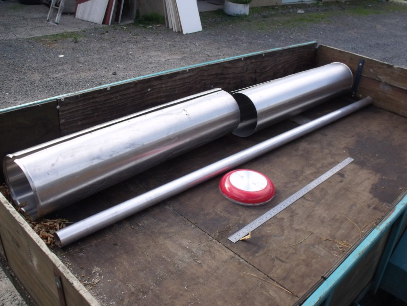
I decided it would be interesting to build a cavity resonator for 29 MHz . I had done many at 2m and 70 cms so it shouldn't be too different . just physically larger !. This was to see what the performance would be .Characteristics such as pass-band. insertion loss . notch depth and the various configurations and the notches they produce .. if this project showed some success ! well I may build three more !!. Im sure we could duplex off two separate antennas with reasonable horizontal separation . I looked up the Net and found the formula for the coaxial dimensions to obtain the best impedance for lowest loss , This was 77 ohms and the ratio of coaxial diameters to produce this is about 3.6 to one . I used 60 mm O.D Aluminium pipe as the centre resonator . I was given some cast off steam pipe , thin walled aluminium thermal jacket tubing . it was 216 mm in diameter . and in length 1.25 m, normally filled with rock wool to thermally insulate geothermal steam conduit ..
Components on the trailer at my brothers workshop Overlapped and screwed together with self tapping screws
. I joined by overlap and self tapping metal screws , two of these lengths to make one of 2.4 m long . I also found a very useful formed Top end-cap structure of substantial rigidity to which I would weld my centre resonator and attach my BNC RF connectors in the form of an inexpensive nonstick aluminium frying pan of 216mm O.D !! ! Check these frying pans out if your building cavity filters of reasonable diameters , as they are an excellent well formed piece of material, cheap and readily obtainable in many different diameters ... don't forget to cut the handle off before you press them into service !!
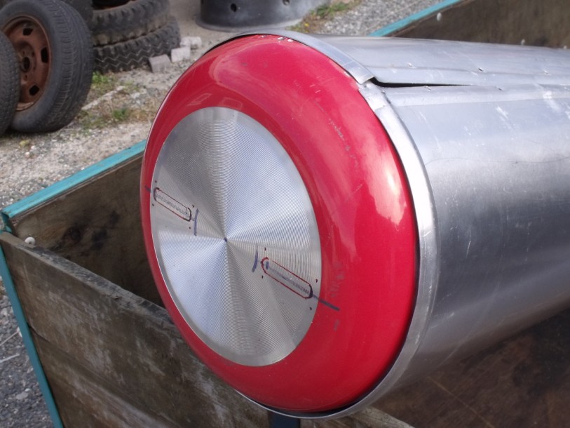
The cheap tiawanese Aluminium frypan ............... without handle Back home....slots in base to insert coupling loops and connectors
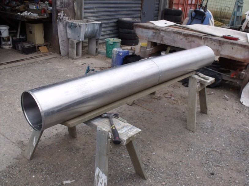
I very good friend of mine Brian Cowien in the Rotorua Classic motorcycle club, to which I belong , was able to T.I.G weld the aluminium resonator the the internal base of the non stick coated pan for me ( coating duly removed before welding ) , It was welded as a continuous bead around the entire circumference of the resonator to provide as low RF Impedance as possible to minimise any losses in this high current region ..
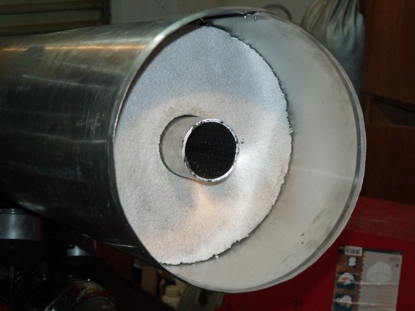
RF Hot end held central with 2 inch thick polystyrene foam disk
It is bloody enormous! and towers above me if I stand beside it ! and one will require a repeater site that has at least a ten foot stud to accommodate the vertical filter . Tuning of this beast in situ , will have to be done using a step ladder !! You will notice that this prototype does not have the ability to tune its frequency response except with judicious application of a hacksaw ! . I want to keep the prototype as simple as possible and see if its RF performance as a coaxial resonator warrants proceeding further mechanically and attaching a trombone / telescoping type tuning mechanism at a later date ..
.jpg)
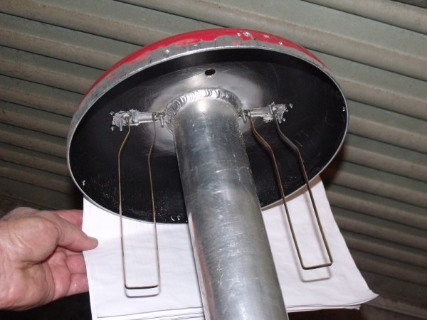
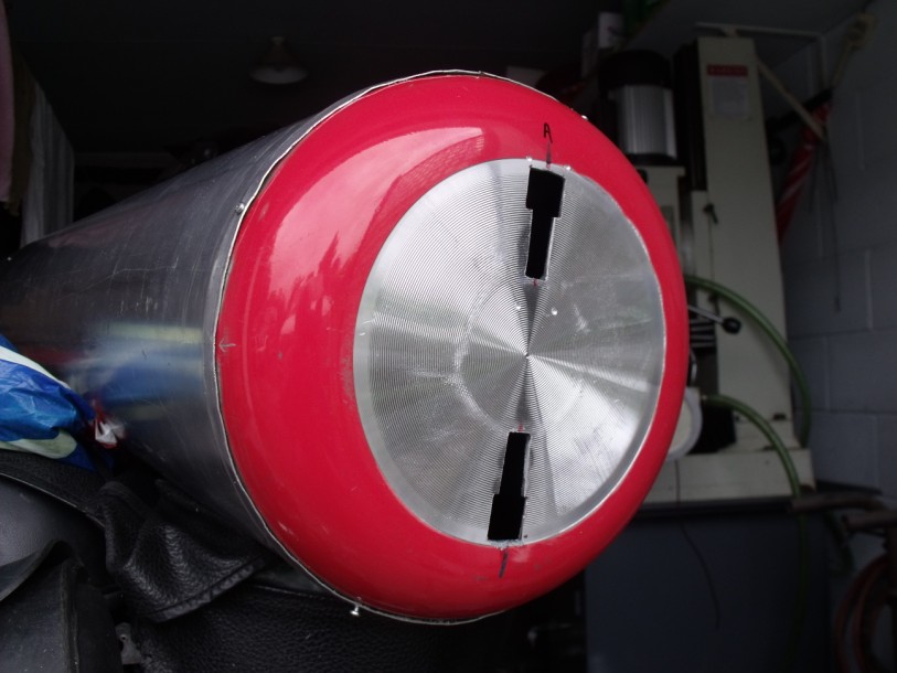
RF coupling loops 170 mm long and spaced 25.4 apart copper strip 6mm wide 1 mm thick ( 2 of ) resonator Welding and loops
OK , finally made and placed the two coupling loops
scaled from the dimensions of a 6 m cavity made by Gary Patterson
NZ5V..... At 29 Mhz These where just under 17 cm long and spaced apart 25.4 mm
I have bent my coupling loops away from the centre resonator to lower the
coupling thus raise the loaded
Q and hopefully better performance with respect to notch depth ,
position and insertion loss . These loops provide too much coupling
, they need to be "smaller" but still a 50 match .
. If I am going to build more of these filters I
will use an RF connector a bit more robust than BNC connectors , N
type ( overkill ) or Flange mount .. SO239 connectors .
But one would have to use double screened coax in application of the
filters to maximise the system performance.
.
Turns out my 2.4 m length of resonator tunes at ~32 Mhz
!! Any way that is no big deal as I can add a telescoping piece to the existing
resonator to make it longer and also I will have to lengthen the outside
aluminium case .. .As it is perfectly ok to experiment with . below is a
loaded sweep of the filter as a simple bandpass showing the 3db points . .
Sweep of resonator loaded with 50 ohm terminations a "QLoaded" configuration
I measured the base level signal going into the filter its from the tracking generator -- Spectrum Analyser as 0.34dB I have bent the coupling loops to achieve around ~0.7 db coupling loss and hope the Q stays up enough to get a reasonable rejection notch , For experimental purposes, the notch was achieved with a length of 50 ohm coax about 0.8 M long between the two coupling loops using T connectors to enable this . I have not optimised this length at all, it was a random length , I will modify the coupling configuration and place a air-spaced variable phasing capacitor inside the top plate connected between the two coupling loop hot ends . this is easier to adjust the rejection notch and loop coupling to enable the optimum result ,
Random length of coax "shorting " input and out put connection
At the moment I have achieved a ~30 dB deep notch 110Khz away from the pass frequency so the system shows promise so far . 100 Khz split is a very difficult one to achieve , 600 Khz at 144 Mhz is a 0.41 % shift ?..439 MHz and a 5 MHz split is a 1.13% shift ? 29.6 Mhz and 100 Khz split is only 0.33 % ? so its a very tall order to achieve the separation and the low insertion loss. The next thing to try is the phasing capacitor that connects the input and output together . inside the top plate and then play the phasing capacitance against the amount of loop coupling and see what we can achieve .I would like to see if I can deepen this notch if possible . I may have to look at increasing the overall "Q" of the system to achieve this .. I will drag out the E5062A VNA from storage and measure the loaded and unloaded Q of the filter and see if we can improve the Q by judicious use of metal crews to pull the overlapped aluminium sheet closer for better contact . VNA's are not the most accurate devices for deriving the absolute Q of the circuit but they do the calculations on the fly and all I want to see is if I am increasing or decreasing the "Q" when I make modifications.. What I want to do is examine the return loss of the coupling loops and to see if we can squeeze more performance of the device by optimising them . I saw in an article by K. Custer ..W8JG ........ about some commercial loops which had their series inductance increased by the judicious use of added inductance .strategically placed (at right-angles) so as not to interfere with main loop coupling if you are going to have a go at building cavity filters and duplexers of various configuration you must look through the Repeater Builder website http://www.repeater-builder.com/rbtip/ Particularly here http://www.repeater-builder.com/antenna/ant-sys-index.html there is a wealth of information to be gained .. I constantly refer to this excellent site ..
Unloaded "Q"
I suspect I should be able to achieve better performance than I am at
the moment but I need to evaluate the unloaded "Q" of the resonator
to get some idea if the filter is good enough . An excellent
article in The repeater builder website by Jacques Audet VE2AZX
http://www.repeater-builder.com/antenna/pdf/ve2azx-duplexerinfo.pdf tells how to derive this You need to couple
to the cavity with small sized loops that give a more than -20 db insertion
loss so as not to load the tuned circuit .
An approximation of the formula is the pass-band centre frequency in
Hertz divided by the actual 3dB bandwidth in hertz .. when I
do the approx maths my "Qu" is only close to ~2800 . that is
not very good for a cavity filter , This is probably
why I can only achieve slightly more than a 30 dB notch at 100 Khz from
the passband .
I now have to look at ways I can improve the "Qu" of
this filter .. First thing I will try is increasing the peripheral
contact between the sides of the "frying pan" and the outer case
.heaps more screws should help here ???? ....
have added more screws around the periphery and got my 3dB
points 1 Khz closer together !! from 12.47 KHz to 11.47 KHz ?
The law of diminishing returns .... I would love to try a
rolled and welded section of thick walled aluminium here but its a bit
difficult to arrange and im trying to build these inexpensively as
not every one may have access to lots of mechanical options ..
To check that I was measuring the "Qu" correctly I performed a measurement on the "200" Mhz ( civil aviation DME frequency in New Zealand ) it was tuned to 185 Mhz approx . the 3db points with very light coupling , greater than -20 dB , were 19-20 KHz this yielded a staggering "Qu" of approx 9200 !! and its an aluminium cavity with silver plated copper centre components inside , I fellow Amateur suggested I remove all the non stick coating from the interior of my 32 Mhz cavity top plate and see if that makes a difference ...I shall do this and recheck the "Qu" But I am pleased to see that the less expensive Aluminium is a suitable material for the project as shown by the sinclair filter performance .
.jpg)
Unloaded sweep >-20 dB loop coupling ( very light coupling) so as not to load the resonant circuit
.jpg)
loops length 70mm by 35 mm inductance to push them near 50 Ohm 5Turn guess
Some of you are looking at the coupling loops side ways !! so take a look here http://www.repeater-builder.com/projects/tx-rx-loops/couplingloopresearch.html any trick to screw the rejection notch deeper !
.jpg)
.jpg)
sweep of variable cap airspaced 100 pf across BNC
centre pins 0.7 dB loss
32 Mhz , 200 Mhz 146 Mhz
Suffice to say considering the
ease and the cost to build this filter I guess that performance figure is
not bad and three of these in each leg of a repeater configuration would
allow use of a single antenna
I suspect two of these filters in each leg , (2 Tx and 2 Rx .)..
good horizontal or preferable vertical antenna separation and one
could use these in a co sited repeater situation
Well I think they are worth making given that the cost of construction and the resulting performance !
The real killer is the Size .......... 73's Mike