Rotorua linear repeater built 1988
Up mixer Transmitter Receiver signal @ -119 dBm
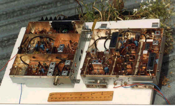
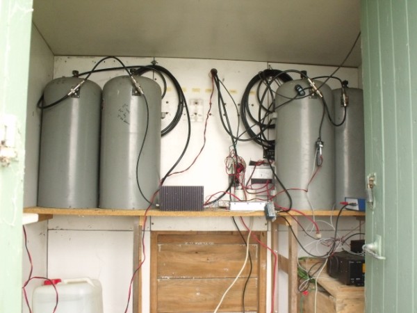
This photo was taken about march 1988, not long after it was all put together and tested. There is a Receiver unit and a separate up mixer transmitter unit . They connected together via a piece of coax carrying the 10.7 MHz intermediate frequency. This unit pictured here is the mark 3 , the original mark 1 was built in a Hudson tinplate biscuit box by Bob Sutton ZL4DO in Dunedin, New Zealand, when we were both living in the same town. I forget the actual transmit receive split but it used CB crystals and it came out to 3.8 MHz or something like that. I remember it was fairly low powered too. I will try and dig out the original article in Break IN magazine NOV 1982 (now in website)
As usual. I didn't keep good notes on the construction of the device back in '88, but I can remember most of it very well, and sufficient of the pertinent information and pitfalls for anyone who would like to build a similar unit.
Receiver.
The front end device was a low noise device, a J310 running in grounded gate configuration and biased to about 10 mA standing current. It had a single 2M tuned circuit , link coupled to the 50 ohm input from the antenna. The output was to a single stage 2 M tuned circuit that fed a 50 ohm RF port of a mini circuits SBL-1 dBm. The L.O. port was fed from the single crystal controlled buffered +10 dBm 137 MHz oscillator via a 3 dB 50 Ohm pad. The IF output was fed through 10.7 MHz L/C duplexer that is designed to present 50 ohms at all frequencies to the SBL-1. the output of the duplexer was connected to another low gain +9dB j310 in grounded gate (Norton configured ) post mixer IF amp to isolate the reactive load of the crystal filter from the SBL-1 , before it feeds the 30 Khz crystal Filter via a 10.7 MHz if transformer . the overall gain from the RF input up to the IF output to the 10.7 IF amp module is quite low ~11 dB or so but I suspect it has a good NF.
The post mixer IF amplifier is to protect the SBL-1 dBm 50 ohm mixer from the high reflected reactance's / impedance's the crystal filter produces to frequencies outside its 10.7 MHz pass-band. Possibly lowering its intercept point and strong out of band signal handling properties. Remember there is not too much front end preselection in the form of 2M tuned circuits (to keep the overall Rx noise figure low). The output of the crystal filter is capacitively top coupled to the if amp 10.7 matching tuned circuit. The IF chain was built using PLESSEY 1600 series IC's The first if amp was a low noise SL1610 . the second and third was using SL1615's. They were coupled together with 10.7 interstage transformers , The PLESSEY RF bible says they can be capacitively coupled together to provide stage gain blocks BUT they produce an awful lot of lot of broadband noise , too much for my liking ,I felt this would upset the AGC action and mean a lot of unwanted RF output on the wanted frequency after up-conversion. The 10.7 interstage transformers help limit the broadband nature of the IF to a few 100's of Khz bandwidth. The last IF amp tuned circuit feeds the PLESSEY SL1623 am detector AGC controller IC . I did not put AGC on the Front end RF amp as this can increase the noise figure of the RX . It is important to remember that after the "wide band" 10.7 MHz IF amp, the noise extends at quite high levels, 100's of kilohertz above and below the center frequency . If this output is not refiltered to a minimum required bandwidth i.e. that of the receive front end crystal filter , then this broadband noise will be upmixed to the new output frequency(144.350)and extend 100 of KHz's either side of the carrier and noise up the receiver reducing its weak signal performance . The quality of the pre-upmixer IF filter can be mediocre with a poor shape factor ,but its bandwidth ideally should match that of the receiver. I used an Identical one like the receive filter .
The up-mixer was a balanced transistor affair , push pull BF199's emitter injection , driven from a simple single transistor overtone crystal oscillator with a buffer stage. the configuration such that the balance is to minimize up mixer local oscillator level ( 137 Mhz ) and reduce it as much as possible. Before feeding the up-mixed IF into a top coupled triple tuned circuit to select for the wanted 144.350 mixer product. From there it fed a J310 grounded gate RF oscillator that was coupled into a bipolar 2N4427 biased into a linear mode these two transistors provide a total gain of 20 dB ( stolen from an article in the European VHF Comm mag , The output of this stage (100mW) drives a typical Japanese linear 2 m power block (100 mW in for around 10W out) we have changed to size of the heatsink to one 10 times the size as we have popped the odd power block ...
Note: to prevent the retransmitted signals, sideband inversion, the up mixer local oscillator must be on the lowerside of the output frequency minus the intermediate frequency. i.e. usb in gives usb out!!
We have two independant crystal oscillators and they both drift interpedently! . Ideally the two oscillators should be locked to hold 600 Khz apart but we had a power budget to hold to and thats what RIT is for anyway ..!
Mute Operation
Our linear repeater site is remote and has only wind and solar power. So it was necessary to devise a suitable mute arrangement that would power down the system, such that only the bare minimum of receiver operated to conserve precious power. However on receipt of a signal, the mute circuit will switch all the wanted upmixer low level amplifier and power block circuitry, back out of class C to linear class A . The type of mute was arrived at after a little experimentation, to use a typical FM noise mute (CA2111AE) , it had quite a fast attack for ssb, could be easily arranged to hang for a number of seconds after loss of a signal. and also by providing an FM demodulated audio output so DTMF tones could be used for control purposes.( you will need an audio buffer on output otherwise the load pulls at the quad coil output ) The audio output also feeds the usual ~10 Khz tuned circuit with rectified DC output and adjustable comparator output .( typical FM radio noise mute) You need about 30 dB or so gain ahead of this chip or it will not function properly , I tapped into the rf output of the second IF amp . Also the loading resistor across the quad coil has a big effect as well , particularly if you are trying to keep a low Q to keep the mute operating bandwidth wide ..
The system is very sensitive and a 0.2uV (-122 dBm) 144.950 MHz signal is readily heard
from the transmitter at 144.350 MHz output. This means that you must have very good
transmitter +40 dBm to receiver , that is a signal difference of 162db !! a
lot of the required isolation will be provided by the receiver being 600kHz away from the
transmitter. However there will be broadband noise produced by the up
mixer and linear
amplifiers, this can amount to many dBms at the input frequency ,this could easily mask a
moderately weak signal on the input frequency. You need to notch out, by many tens of dBs
, the transmitted broadband noise at the receive frequency i.e. the broadband noise
caused by the transmitter at 144.950 MHz, and place a rejection notch in the receive
signal path to remove any signals at 144.350 MHz to stop the transmitter causing
intermod and overloading in the receiver. To operate a 10w output repeater
effectively, you require about 110 dB of isolation between the transmitter and
receiver. This isolation is achieved by utilising High Q ,low loss tuned circuits, usually
in the form of multiple coaxial cavity filters (see section on coaxial cavity filters
elsewhere in the website) a minimum of two in the transmit coax and two in the receive
coax are required , and the rest of the isolation provided by utilising separate receive
and transmit antennas. By using three cavity filters in each feed line and a circulator
for added measure you can run the entire repeater off one lone antenna!!
I have done some tests from home using my Agilent signal generator
N9310 into my 2 5/8 collinear on the roof of my shed . I
connect the roof antenna to a 140-160 Mhz circulator and connect the E4403 Spec
An on one port and the N9310 sig genny on the other , I have at least 20 dB
isolation between the signal generator and the spec An .I can see both signals
together on the screen .
ZL1PJ at test set -80 dBm into the repeater 12 W output ( max)
The repeater has been reset to open ay -118 dBm ( measured at the site ) according to ZL1PJ 's operating his HP8920A test set , and the minimum signal from home line of sight to the repeater is -26 dBm to just open the squelch ! shows you how far a weak signal travels too !
-22 dBm into my antenna yields a -61 dBm return signal with a
15 db signal above the noise .
H ere are some latest figure Jan 2010 ,
the average noise passband sits at about -75dBm level (
equates to 1.5 W output to the 2 5/8 phase collinear )
-34 dbm gives -70 dbm at home antenna (9 Kms away)
-22 gives -63, -16 gives -57. -13 gives -55 , -10 gives 54 and -7 gives -54,
I suspect we have hit the AGC level and from now on the peak received signal
level out does not increase but the broadband IF pedestal starts to drop
away and the signal to noise improves as the pedestal falls to the
-100 dBm floor of the analyser display giving a maximum of 45 dB sig to
noise .. see our repeater passband has been tuned up off frequency
.......not guilty ! Once the mute is open (
and it hangs for about 2~3 seconds ) you can see the weaker signals on the
display its just the weaker signals will not open the system .There
is passband ripple because the repeater has two crystal filters ( 7 pole )
one after the receive mixer and one before the transmit upmixer and we
have found the system is more sensitive in different parts of the passband
--26 dBm into the home antenna will just open the mute at the most sensitive
region .
While the unit was on the bench at home having a mute rebuild I did some measurements
RF input dB above IF noise passband Bird watt meter
-123dBm
10
2.5W out
-120
15
4.75
-117
18
7.5W
-114
21
10.
-111
23
11.5
-100
28
11.5
-90
45
12.0
-70
50
12.0
A circulator is a passive frequency selective ferro magnetic device with three
ports (connectors) that has the ability to split and divide the RF signals depending
on the direction the signals are going, and direct them to different ports or
connectors. you can get up to 30 dB isolation between two ports on a circulator and only a
few tenths of a dB loss in the process they are not cheap
to buy new but
sometimes surplus ones seen at junk sales as not many people know what they are.
The Rotorua Linear repeater uses two collinear element
verticals as a
omnidirectional repeater stacked about eight feet
apart one above the other ,this gave a measured isolation of about 40 dB . Thus we
can easily achieve our 110dB isolation without difficulty . Watch the quality of the feedline coax used preferably double screened but keep the TX and RX coax well separated
to minimise unwanted coupling, you can loose precious TX RX isolation this way.
The RF output to the antenna is approximately 8 W ( Bird watt
meter) after the two Sinclair cavity filters
The Audio through the system has to be heard to be believed It sound excellent , just like a "simplex quality " contact as no audio processing is done because everything stays at RF

Rotorua City some Kilometers away to the south west ( 9 Kms
L.of.S to my QTH )
click to return to HOME PAGE
![]()