Amplitude modulation of 2.5 GHz WBFM systems M.A.PINFOLD ZL1BTB
Oct 2021
This is an experiment
to assess the suitability of transmitting SSB carrier at 1.65 Mhz
I.F by way of WBFM at 2.4 GHZ and demodulation said WBFM signal and
recovering the 1.6 MHz SSB signal from the video out of the 2.5 GHz
receiver .
I am building a mk 2
H.F SSB repeater to use on 80m or 40m and you may ask why a
repeater on HF.. The answer is for exactly the same reasons as there is the
reasons for repeaters on VHF/ UHF.
Just like simplex on
VHF / UHF , mobile to mobile on HF can be very difficult however
a mobile to base station with a full sized hf dipole can provide good
communications so if we can provide a system of mobile 1, to base
dipole and then base dipole to mobile 2 this should increase the
S/N between both mobiles .
A repeater can be
achieved by connecting the HF receiver audio output to the
transmitter audio input with an offset frequency between them. You
then run into problems of close freqency separation and interference
between the transmitter and receive , just like VHF...UHF . There are two ways of
minimising transmitter receiver interference, you can build up
some highly selective transmitter and receiver filters which I did
in the MK1 HF repeater ., this was somewhat difficult,
complicated and frequency stability was the main problem, I did
achieve 90 dB isolation through the filters, but with the
transmitter and receiver somewhat physically close T/R isolation
was at the forefront . I would not be confident I could have built
up this system as a remote setup without a lot of periodical
maintainance and tuning .
The easy way out is to
remotely site the transmitter and receiver many Kms apart to
achieve good physical isolation and connect the audio between them . In the old days ,
remote transceivers HF and VHF in the country with full size
antennas were controlled over a post office copper pair ,the
transmtted and received audio were sequentially sent up and down the
copper pair via the pots network to the central office in town .I
cant do this without investing money in line rental , so I had to do
it another way .I decided to make the
mk2 hf repeater out of the usual two 7727 codans but I would strap
the 1.65 MHz I.F of the receiver and transmitter together and not
do any audio demodulation , By staying at IF you reduce the number of
frequency conversions thus potential quartz crystal drift and use of
the clarifier at the mobile end , and keep the S/N at maximum .
I did some tests
between our branch33 HF remote receiver ICR75 on a full dipole and
my Icom 706 on 80 m Dipole about 12Kms away and found I could
waltz up to less than 10 Khz away from the received frequency and not
detect any splatter or interferrence . I need to try the test again
when the hf remote is listening to a somewhat weak HF SSB and see
what are the effects if any . Now becomes the problem
of strapping the transmitter 1.65 MHZ I.F to the receiver .Direct
connection is impractical so the connection has to be by RF , I did
not want to link on vhf or uhf because we are back to crystal drift
in multiple conversions .
I then had the great idea of using a 2.4
GHz video transmitter and its matching Receiver, These units
transmit a video signal with a bandwidth up to 7 MHz . Modulate the
transmitter video input with the 1.65 I.F from the HF receiver ,
transmitt it over the line of sight distance and then take the 1.65
MHz I.F out of the 2.4 GHz video receiver video output port and into
the transmitter I.F . The great thing is
there is no baseband frequency shift in this process. One could
also transmitt 455 Khz this way as well . The video sender system has
the ability to transmit two separate audio channels as well, these
could be used for transmitter control ??.
Most video sender claim
a video S/N of up to 50 dB when the 2.4 GHZ signal is in full
limiting I feel this s/n is more than enough for this HF.purpose ..
I will now try a range
of signals and see how well they pass through the 2.4 GHz system.
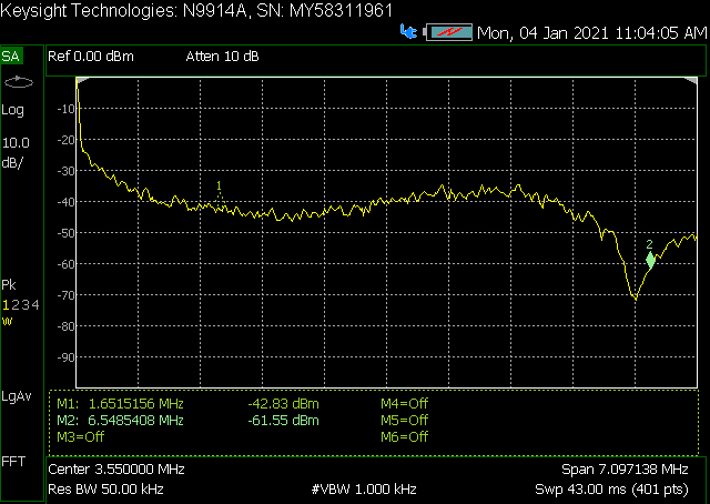
Broadband noise from 75 ohm video port
into 50 ohm Spec An
video noise output, receiver in full limiting from 2.5GHz signal Signals at 455 Khz and 1.65 Mhz were connected from a signal generator to the video input of the transmitter and the demodulated 455KHz and 1.65 MHz signal observed on the spectrum Analyser. Antennas on the 2.5 GHz units were terminated in 50 ohm SMA terminations .
The 2.5 GHz units were next to each other on the bench ..
-60 dbm baseband into 2.5 GHZ Tx shows -64 dbm out of video receiver
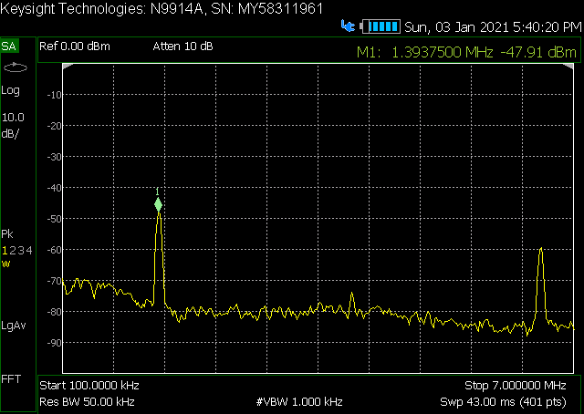
Video receiver output at 1.4MHz shows good S/N
Provided the 2.5 GHz receiver stays in limiting, the unwanted noise output will be better than -70 dbm , the wanted SSB signal will be a good useable S/N above this ,it would be advantageous to make a simple 1.6 MHz bandpass filter to bandlimit unwanted ouput signals .
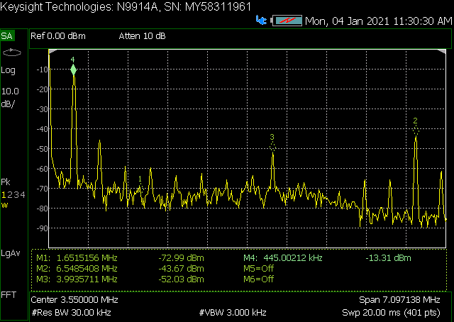
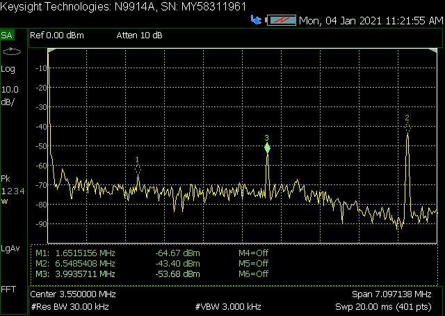
The input signal level at 1.65 MHz and 455 Khz to the 2.5 GHz
transmitter was varied form -70 dBm to 0.0dBm and the output of the
2.5 GHz receiver monitored on the spectrum analyser.
455 KHZ at -10 dBm (max) …. note
spurii have now appeared
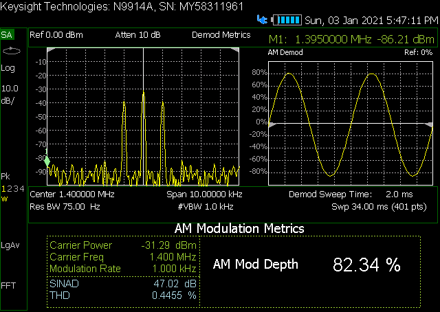
80% mod A.M note sinad and THD so should be ok for SSB
Tx Input dBm 1.65 /0.455 MHz RX out dBm 1.65 0.455 MHz
-60 -65 -63
-50 -54 -53
-40 -44 -43
-30 -34 -33
-20 -23 -24
-10 -13 -14
0.0 -3 -3
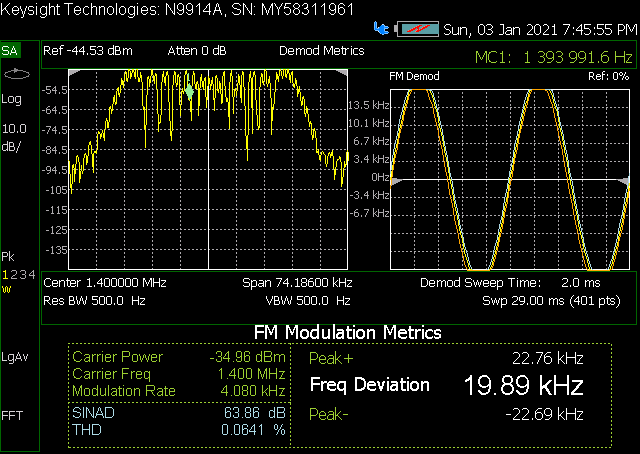
note the SINAD and THD running F.M through the system!! .link some F.M repeaters too ??
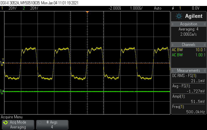
I decided to poke some digital square waves from my HP function generator .. max seems about 2 MHz this was a simple test , no doubt through put could be improved with the correct interface electronics . As the frequency went down the scope screen looked better and better , High frequency distortion of the square waves due to just lack of bandwidth . Now you see why WiFi systems have to be so broadband to achieve the data speeds they operate at !!
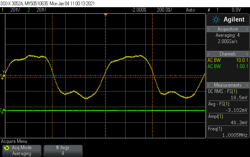
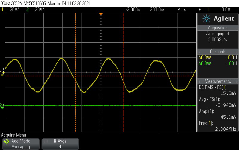
I guess these are respectable square waves but they are not at digital levels but it wouldnt take much level converting to achieve this .
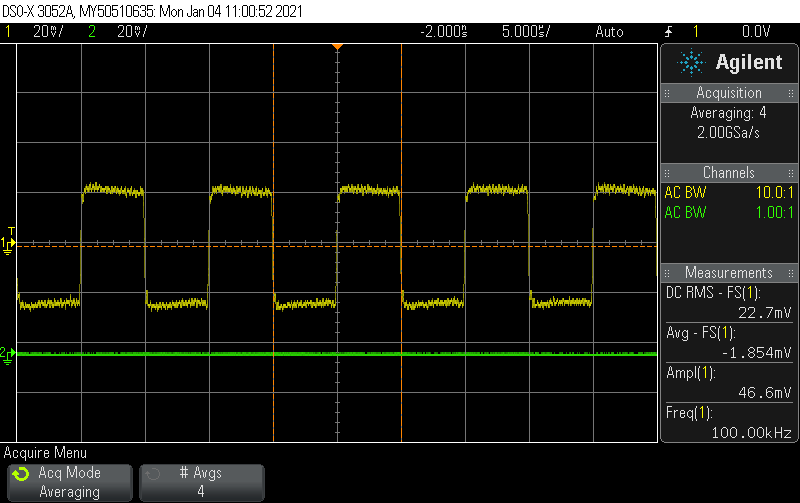
100 Khz output
All that remains is to feed the correct levels if I.F at 1.6 Mhz out of the HF codan Receiver I.F strip , I may us the dedicated 7004 single channel receiver ,and put a BNC out put plug with a simple low impedance buffer stage to connect to.
The next thing is to feed the received 1.6 MHz into the up mixer in the transmitter through the 7727 crystal filter, to filter away all the broadband video receiver I.F noise ,otherwise the broadband noise will add to the transmitted signal and just be an unwanted nuisance .
Food for Thought !!