Circulators:
No this is not another name for water pumps or teaspoons but what
is technically described under the term of a non reciprocal junction. It is usually
a three port ferro-magnetic device and it has distinct directional properties from port to
port. They are usually seen as a block with three rf connectors on each corner, or
sometimes two however one of the ports may be internally connected to a resistive load
usually 50 ohms.
CIRCULATORS IN VARIOUS FORMS
Operation: The three
port device (think of it as a triangle) relies on the fact that because of the ferro
magnet coupling inside, rf energy is diverted in a direction from port 1 to port 2 but not
into port 3, however if you swapped the connections over there would be great resistance
to the signal flowing in the opposite direction from 2 to 1, it would rather flow
from 2 to 3. This feature occurs on all ports so you end up getting a
"directivity" traveling in one direction around the triangle.: One immediate use
that springs to mind is that of an automatic "gate" that can distribute the flow
of signals from and to an antenna and that is a common use of the circulator. The ports
have a measure of directivity or "isolation" measured in dB. eg a port to port
isolation of 20 dB means that it conducts rf in one direction 100 times better than it
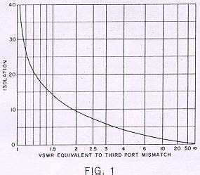
does in reverse.The most
misunderstood concept of circulators is that of isolation.
Circulators do not provide isolation until they are terminated, and then the
isolation between any two ports ( in the direction opposing the direction of
circulation) is the return loss due to third port mismatch.
Conect one port to an aerial one port to a receiver and the other to a
transmitter (observing the directivity of course) and you immediately have 20 dB isolation
of your transmitter and receiver. simple huh! but there are a few constraints .They
have loss and they are frequency concious. typical loss of a matched circulator is
usually measured in decimal fractions of a dB. Circulator operation is usually specified
over a certian bandwidth of frequencies, i.e. the amount of isolation in dB
over the frequency range it will provide the minimum value of port to port isolation. In
order for the device to work as specified, it must be terminated in the designed
impedance, typically 50 ohms.There are of course other designed impedances ie those
circulators that are used in microwave waveguide.
INSIDE IT:
IN the VHF-UHF circulator, the coupling between ports occurs in
flat insulated overlapping terminated copper sandwiched striplines that are positioned 120
degrees in rotation apart. see picture . These flat copper striplines are sandwhiched betweeen two disc shaped
slabs of a ferrite material whose composition is optimised for the ferro-magnetic effect.
There is a strong magnetic feild placed accross the discs such that any rf energy flowing
in the striplines has to enhance or oppose this biasing magnetic feild, that is how the
directivity is generated. The magnetic feild strength also has an effect on the frequecy
of operation, and the degree of isolation. This change in magnetic feild will
change the permiability of the ferrite that encloses the coupling striplines and alter
their performance . The physically larger the coupling lines and ferrite discs, the
lower the frequency of operation , the small one I pulled to bits is out of 900 mhz
equipment, cell phone I think,
Now you see all the variables
you have to play with! It can be a real headache juggling these parameters to acheive what
you want. It is important that the circulator is tuned into the correct impedance
if it is going to function as you would like it to perform. If you perform your tests and
tuning using 50 ohm termination at each port , All the repeater terminations
must be 50 ohms resistive or the circulator will not perform well.
Circulators used at VHF and UHF (if you are lucky) may have
internal matching networks, usually in the form of L/C or just variable trimmer capacitors
. This is a boon as it means you will be able to shift the devices operating
frequency and change its degree of port to port isolation. Circulators picked up at junk
sales tend to be produced for commercial frequencies (as that is where the money is ) In
case you are wondering what they cost to buy, it is in the many hundreds of dollars region
for a device used on the standard commercial 20 W repeater. Purchase circulators as
close to the frequency of intrest as possible, then you are more likely to have some
degree of sucess in your venture. I found the best way to tune them, is to terminated all
ports in 50 ohms and then tune for maximun rejection of signal at the wanted frequency
(with the circulator connected in "reverse") then rotate through all three
ports tuning for the same . You are wasting your time trying to tune in the forward
direction you will just go round and round in circles getting more frustrated ( took me
quite a few days to discover this!)
A properly tuned circulator on a repeater system can add up to an
extra 20 dB transmitter/receiver isolation to that provided by the duplexer filters
and only increase the system noise figure by a small fraction of a dB(0.2-0.4 loss through
the circulator). They have another excellent use as well. If you place a suitable 50
ohm load on one port and place the circulator in the transmit feedline (with respect to
the correct directivity), then if the antenna developes high SWR, the reflected power will
be diverted back around into the 50 ohm load and the transmitter, protected from damage.